17
General
F-FEM-DDC — User’s Guide
2.4 Visualization
The data sampled by the F-FEM-AIx modules is visualized in connection with the
AVL PUMA system, using the program POI (Puma Operator Interface) under
Windows.
You will find further information from POI User’s Guide.
2.4.1
Status LED at the front side
At the module front down to the right there is a green LED, that announces the
existence of the operating voltage. Further functions that are dependent on the
installed firmware are described in the SW Release Notes.
LED is ON: F-FEM is provided with voltage
LED is OFF: F-FEM is not provided with voltage
LED blinks: Identification of F-FEM is activated
2.4.2
Status LED at the rear side
There are 6 LED at the rear side of the module with these functions.
If the identification of the respective F-FEM is activated, all LED blink synchrono-
souly at the rear side (except LED 1).
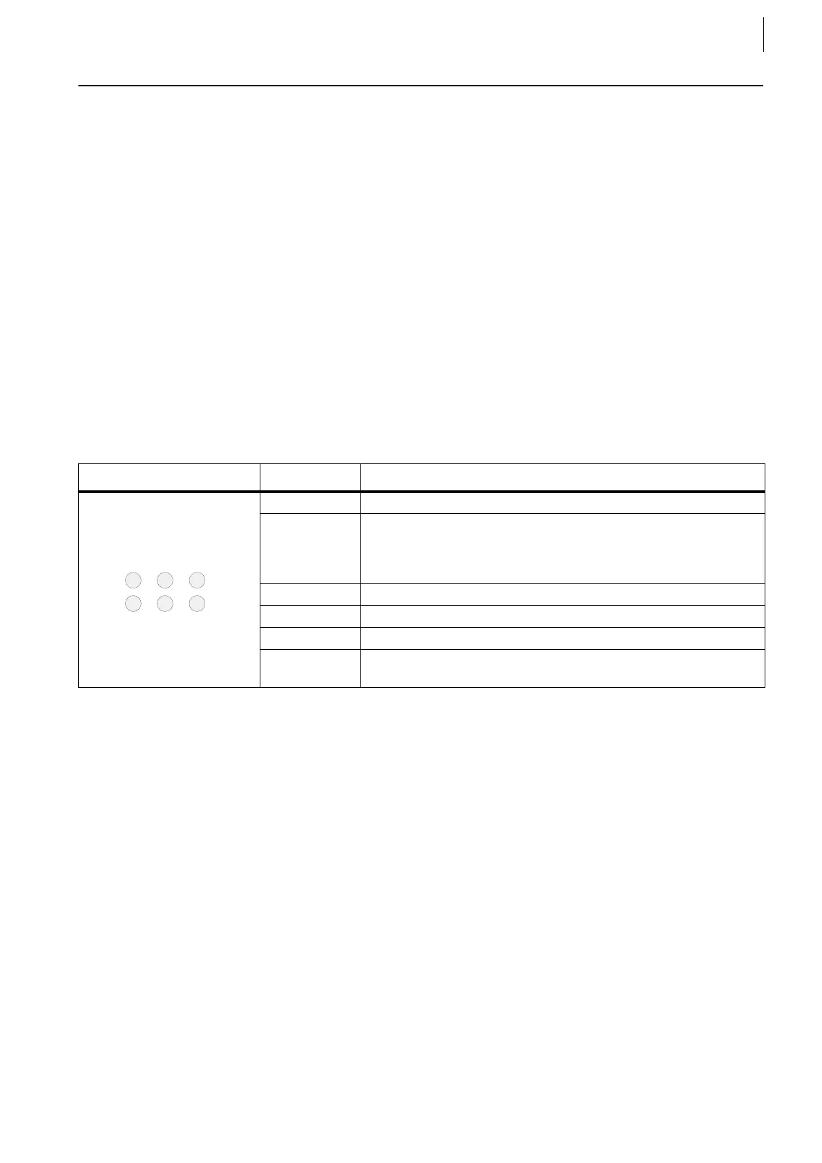
Layout LED No. Description
1 "Happy LED“ = FPGA loaded, blinks with 3 Hz
2 „Blinky“ = 1 Hz blinking
Trigger for all F-FEM-AIx blinks with 1 Hz
Trigger master: short time dark
Trigger slave: short time light
3 „TX“ = Transmit LED blinks on each thousandth data package
4 „RX“ = Receive LED blinks on each thousandth data package
5 „Load“ = CPU utilization
6 „SW Download“ is running
Do not break power while downloading!
Tab. 1
 Loading...

