Options
64
F-FEM-DDC — User’s Guide
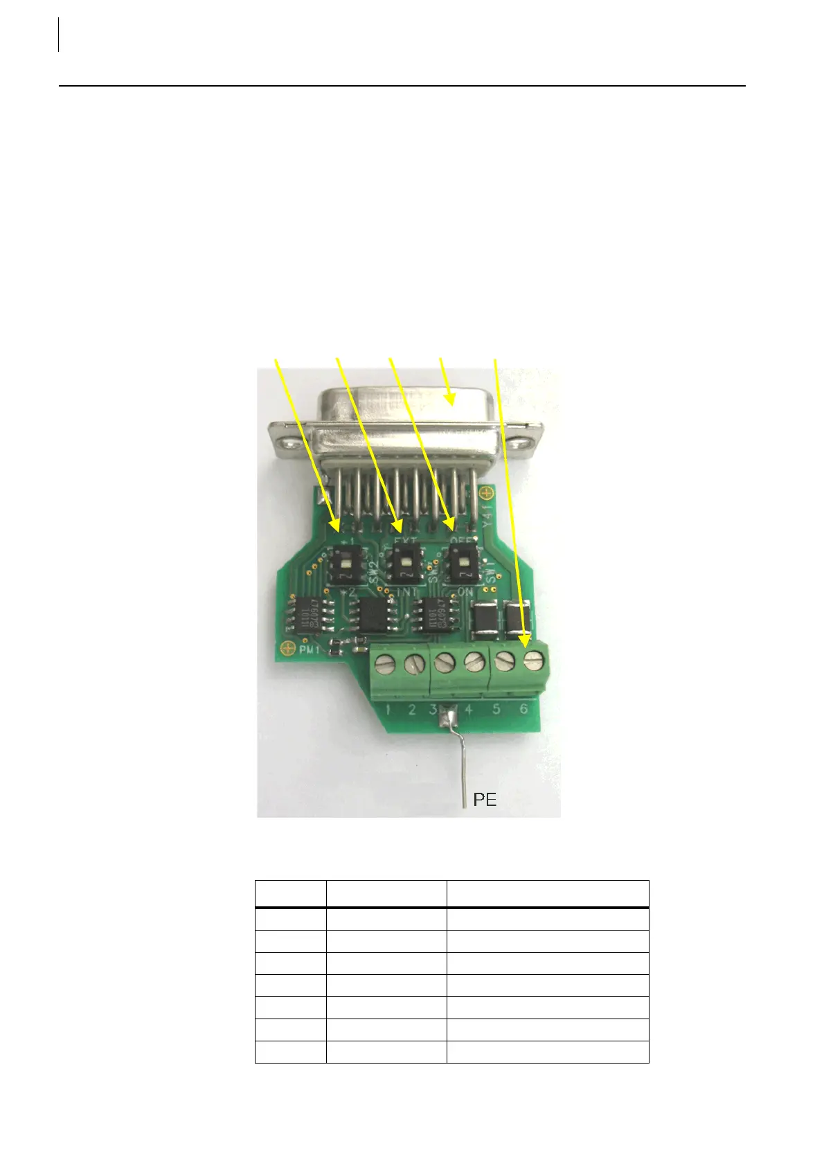
5.4 Counter Signal Adapter "CSA-Connector"
This adapter unit is for different speed sensors, that does not fulfill the required
specifications for the digital input of the F-FEM-DDC. It consists of two compar-
ator-inputs that can be connected for differential or single ended signals and it
feeds one two-track counter channel on the F-FEM-DDC over the Bits 1 and 2.
The Bits 3 and 4 are not accessible in this case (they are mapped to the second
counter channel).
The sensor wires can be connected via screw terminals (J1), the components
are housed in a Quick-Lock hood for direct mounting to the F-FEM-DDC digital
counter inputs (X41-X44) or via a cable also connected to the F-FEM-CON (X17,
X18) or to the F-FEM-CNT (X17, X18, X29, X30).
Counter Signal Adapter:
SW2 SW3 SW1 Y41 J1
Fig. 42
Pin Signal at J1 Remark
1 TrackA +
2 TrackA –
3 TrackB +
4 TrackB –
5V
CC
5 ...24 V in, or 24 V out
6 GND In or out
Case Shield Shield
Tab. 27
 Loading...

