Operation
44
F-FEM-DDC — User’s Guide
4.4.2
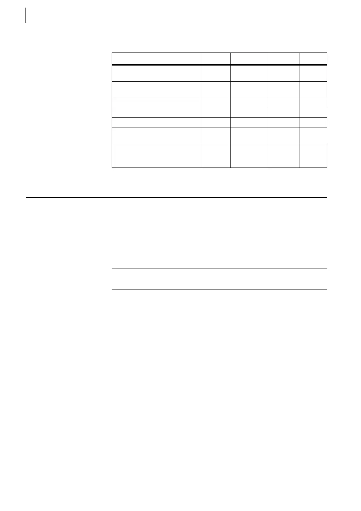
Specification
4.5 Digital Outputs Transistor
The transistor outputs are designed for higher switching frequencies than relay
contacts. Industrial high-side switches are used for sourcing current, sinking
current is not possible.
If the current for your application is too low, you can connect more than one
channels in parallel. The total current is equal to the sum of the single channels.
A maximum of 4 channels can be connected in parallel.
Measured Quantity Min. Typical Max. Unit
Operating voltage 24 60
42
V
DC
V
AC
Switching current
for resistive load
1A
Relay operating frequency 2 Hz
On Resistance 0.17 W
Operating cycles 10
5
Output voltage at Pin 1, 2 of
X51, X52
U
supply
– 1 V
Output current at Pin 1, 2 of
X51, X52
for each connector
2.0 A
Tab. 12
Example
If you connect 3 transistor channels in parallel, you can switch up to 2.1 Amp.
 Loading...

