25
Installation
F-FEM-DDC — User’s Guide
3.3.3.2
Recommended Bus Topology
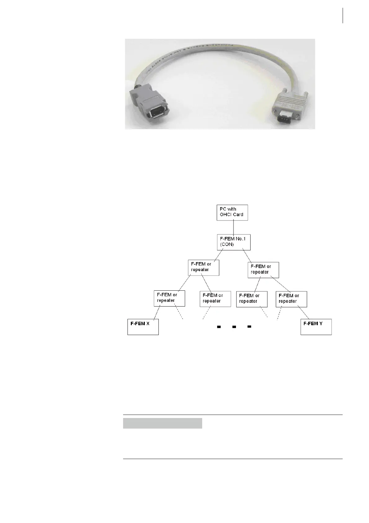
Fig. 9 shows IEEE1394 wiring as recommended.
In PAM, the F-FEM that has the number 1 should be next to the test bed work-
station, most commonly the F-FEM-CON.
3.3.3.3
About F-FEM Devices, Nodes, Cables and Repeaters
The maximum distance between any two nodes (e.g. F-FEM devices) must be
no more than 16 cables.
Example
In Fig. 9 the distance between F-FEM-X and F-FEM-Y is 6 cables.
Each repeater counts as one node, like the test bed workstation or an F-FEM.
Fig. 8
Fig. 9
Information
You can use multiple repeaters to reach distant F-FEM devices if the cable
length is too short. (from PUMA Open Release 1.2, Order number is
TP08BB011B.01)
 Loading...

