General
18
F-FEM-DDC — User’s Guide
2.4.3
Seven Segment Display
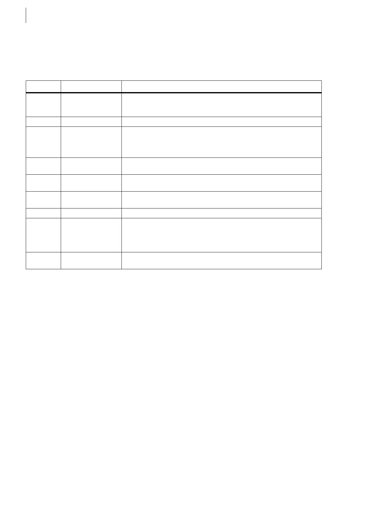
Also at the rear side of the module there is a binary seven-segment display,
where different characters are displayed depending on the operating mode.
The table below gives an overview of the displayed numbers and their meaning:
Display Function Description, Remedy
. . Hardware reset Is shown briefly when the module is started (for approx. 2 - 3 sec).
Intermittently flashing dots indicate a hardware fault. Please send the
device in for repair!
Bl Boot-Load A new firmware is being transferred.
Fl Flash The new firmware is being stored in the permanent memory (Flash
EPROM). This takes approx. 15 seconds. During this time, the power
supply must not be interrupted, as otherwise an incomplete system
would be created which cannot be rebooted.
F-xxx F-FEM No. The parameterized F-FEM number of Config table is displayed at PAM,
dependent on the employed version PUMA-open
S-XXX F-FEM
Serial number
It is needed with the parameterization in the Config table.
e.g.: S-123
H-XXX Hardware
Revision number
e.g.: H-350
r Root The Clockmaster is the corresponding F-FEM
Depending on the firmware used there may also be other characters
that are displayed, e. g. a scrolling text from right to the left. They are not
relevant for users.
If errors occur, error numbers will be displayed (e.g. E1, E2, ...).
8.8.
(blinking)
Identification The identification of F-FEM has been activated.
Tab. 2
 Loading...

