75
Options
F-FEM-DDC — User’s Guide
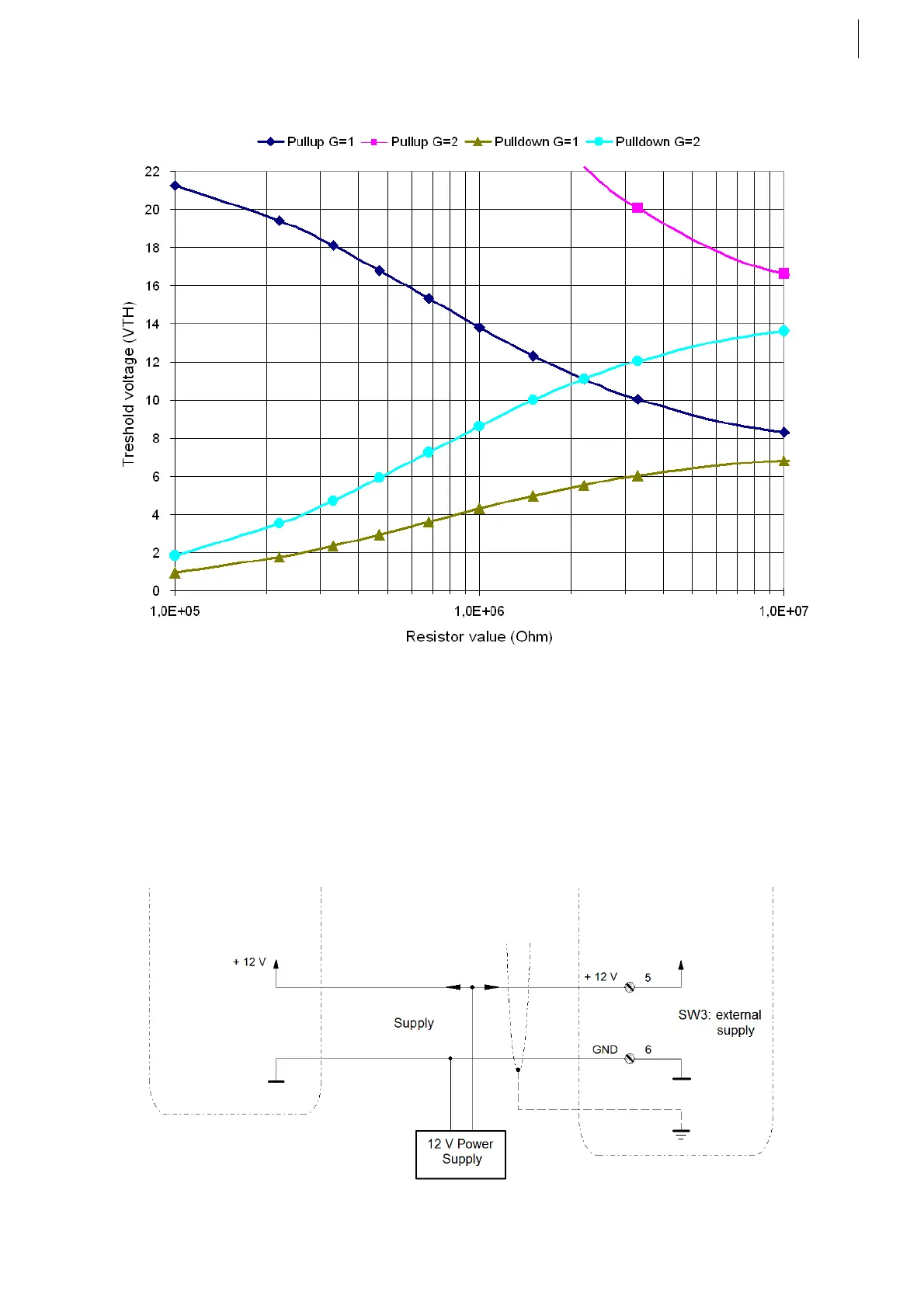
Adjusting the threshold voltage:
5.4.8
Using a different supply voltage
The Pins 5 and 6 of J1 are the supply pins of the counter signal adapter. They
can be used as outputs (using the supply coming from the F-FEM connector to
supply a sensor) or as inputs (in case of the need of a galvanic isolation between
the sensor and the F-FEM supply). This can be distinguished via the switch
SW3: internal or external supply. Please see the Tab. 30 on page 67.
Connecting a sensor with e.g. 12 V externally supply:
Fig. 53
Fig. 54
 Loading...

