Options
74
F-FEM-DDC — User’s Guide
Using a resistor for a variable threshold:
As you can see on the internal block diagram of the CSA (see Fig. 44 on
page 66) there is a resistor divider on the track– inputs to get a default threshold
voltage.
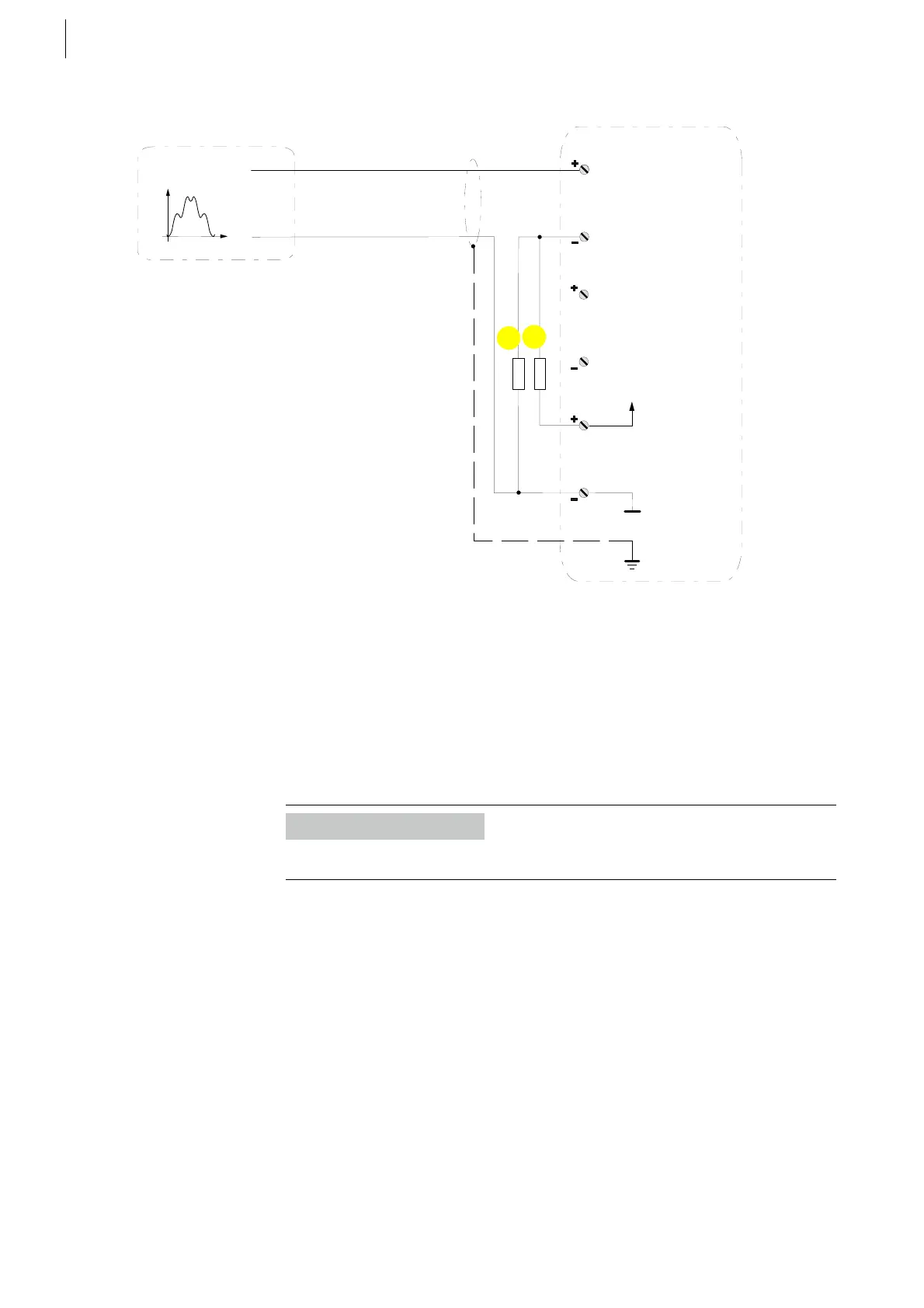
In the following figure some resistor values are shown with the corresponding
threshold values based on a supply voltage of 24 V. To rise this value up,
connect a pull up resistor (2), to lower it, connect a pull down resistor (1) exter-
nally like shown in the Fig. 52 above.
For other supply voltages than 24 V simply scale it with
V
TH
= V
TH24
* V
SUPPLY
/ 24
Fig. 52
Track A
J1
5
3
4
6
SW1: open
SW3: internal
supply
CSA
1
2
arbitrary
Sensor/signal
*1) *2)
SW2: Gain * 1
or * 2
1 external pull down resistor
2 external pull up resistor
Information
Only one resistor - either a pull up or a pull down must be used.
 Loading...

