Options
66
F-FEM-DDC — User’s Guide
5.4.2
Block Diagram
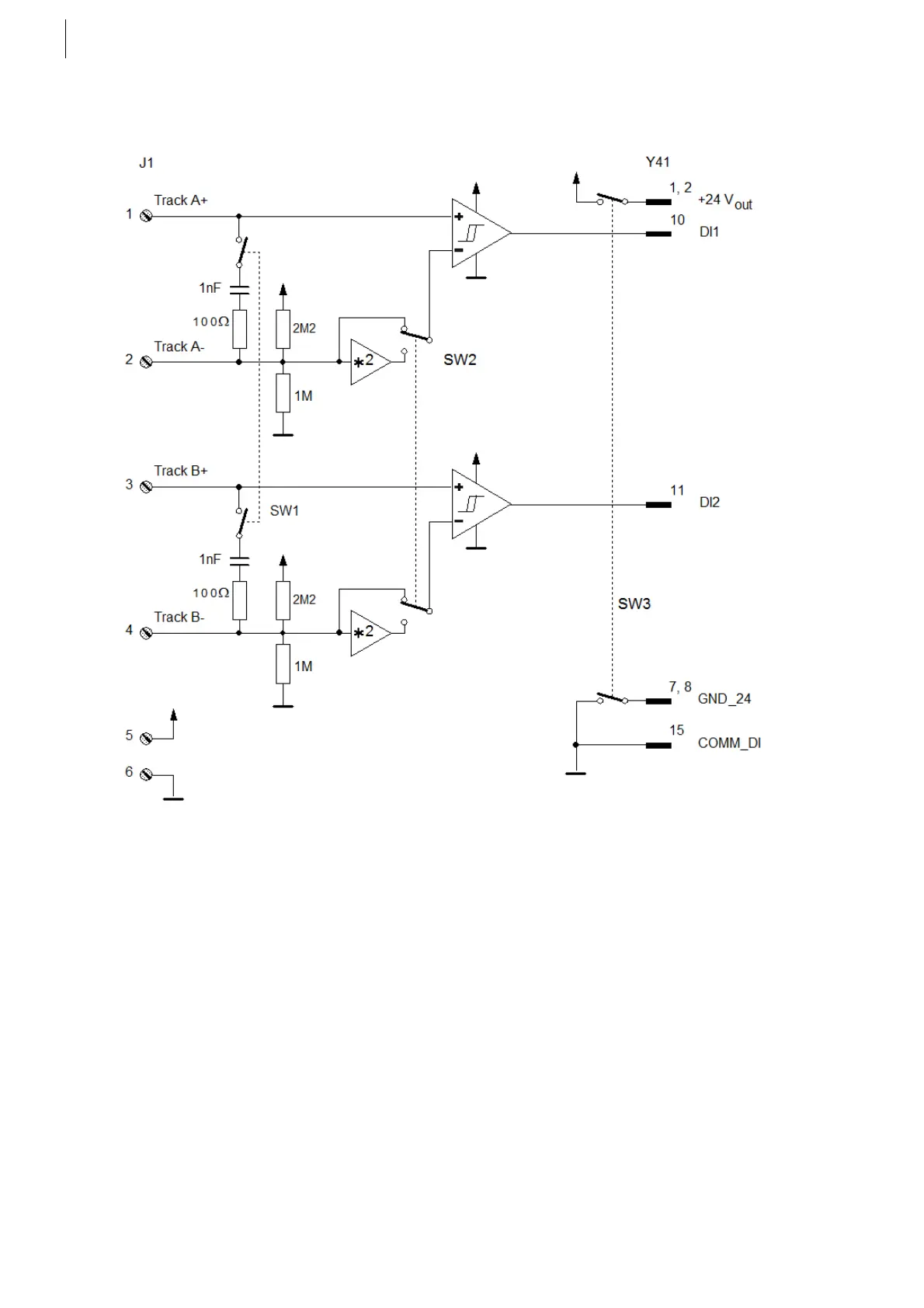
Counter Signal Adapter block diagram:
The block diagram does not show all parts, only the most important ones that are
necessary for the functional understanding.
On the left side the sensors are connected to the screw terminals, the RC termi-
nation is required for a RS422 incremental encoder connectable via SW1. The
voltage divider with 2.2 MOhms and 1 MOhms gives a default threshold value of
1/3 * V
supply
. when used with a single ended signal. With the following Amplifier
with a factor of 2 this threshold can be multiplied to 2/3 * V
supply
. Depending on
the position of switch SW2.
The comparator is the core of this adapter that outputs a "logic one" if the +input
is higher than the -input, or a "logic zero" vice versa. The hysteresis is not adjust-
able, but varies a little bit with frequency.
The switch SW3 can be used if a different supply voltage (other than the internal
24 V) must be used for the sensor. Supply voltages from 5 V to 30 V are
possible)
Fig. 44
 Loading...

