Operation
36
F-FEM-DDC — User’s Guide
In the block diagram above only the most important elements are shown. The pin
out is shown for X41, but it is the same for X42, X43 and X44.
4.2.2
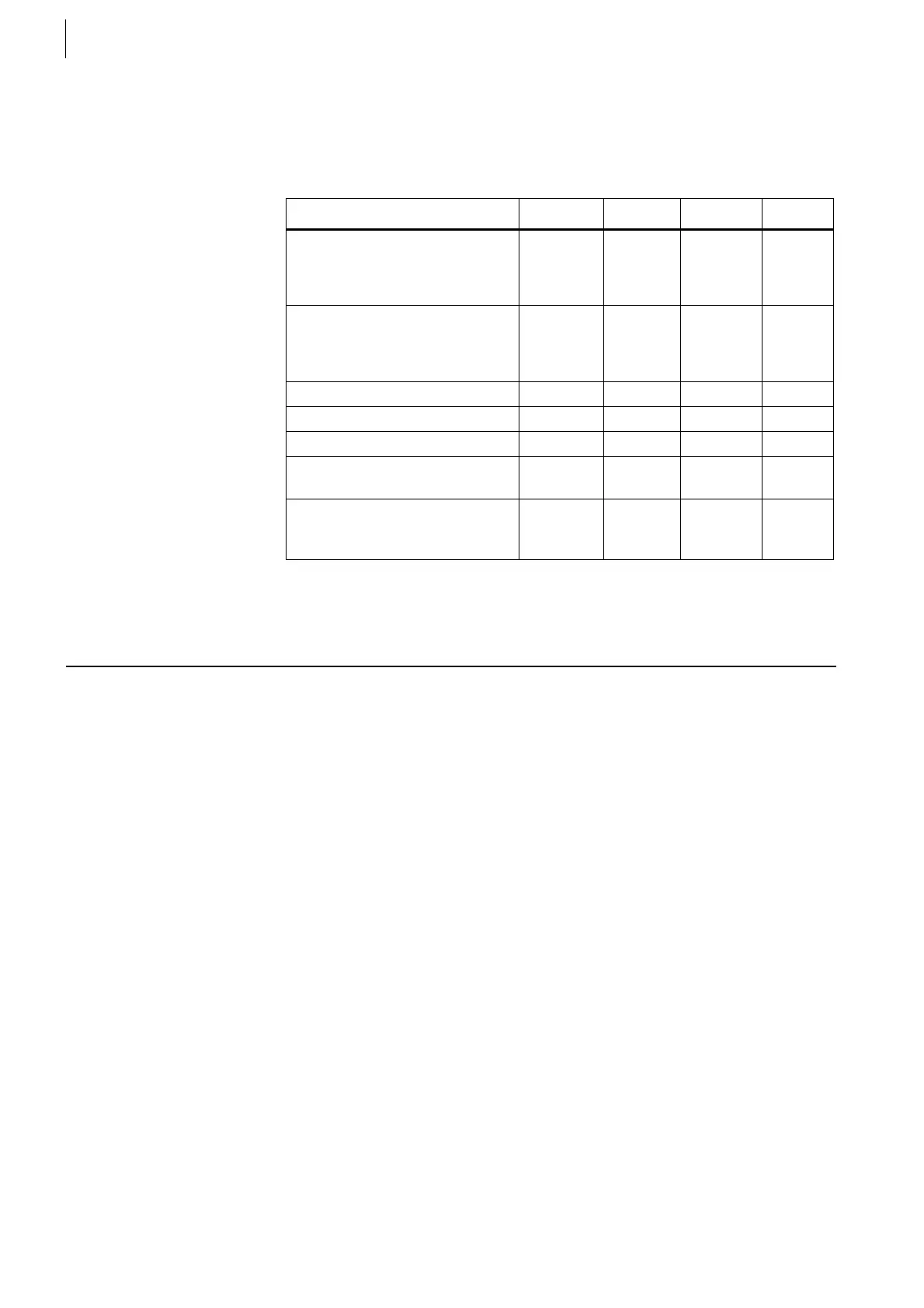
Specification
4.3 Counter Inputs
The F-FEM-DDC has 8 counter channels (one or two track) that are fed by the
16 digital input channels.
In addition, these Counter inputs have parameterizable digital filters for elimi-
nating spikes of variable length. This filter function is available only with PUMA
Open Version 1.5.1 and upward and described in the chapter Spikefilter on
page 38.
Measured quantity min. typical max. Unit
Input voltage at logic low
Internal supply relay cleared
Internal supply relay set
2.0
10.0
V
V
Input voltage at logic high
Internal supply relay cleared
Internal supply relay set
4.0
15.0
60
60
V
V
Input current at logic high 2.0 3.5 mA
Pulse width for DI 1500 μs
Input Frequency for DI function 0.4 kHz
Output voltage at Pins 1, 2 of
X41, X42, X43, X44
U
supply
- 1 V
Total Output current at Pin 1, 2
of X41, X42, X43, X44
for all 4 connectors together
2.0 A
Tab. 9
 Loading...

