47
Operation
F-FEM-DDC — User’s Guide
4.6.1
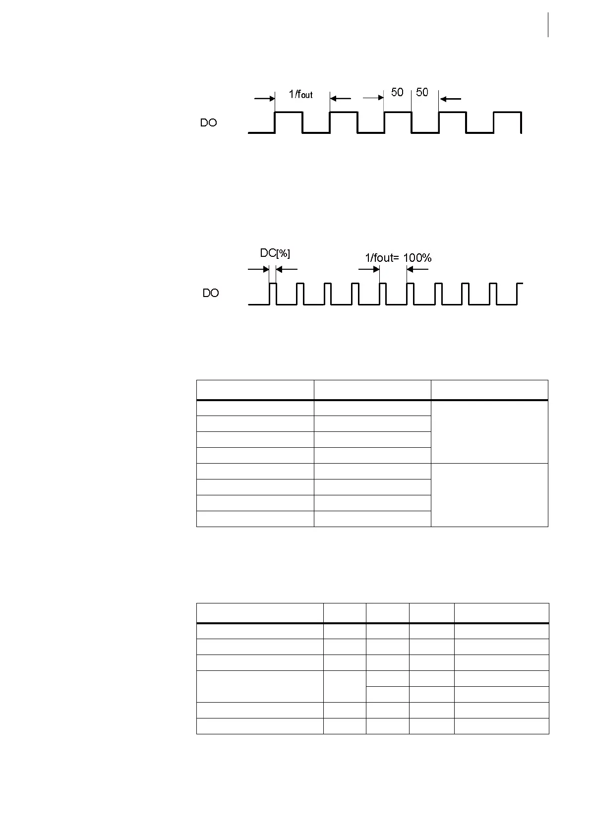
Signal Type: Freq
Eight individual frequencies can be generated with a maximum of 5000 Hz. The
duty cycle is about 50% fixed.
4.6.2
Signal Type: PWM
Eight individual signals can be generated with a variable duty cycle and a
maximum frequency of 500 Hz.
4.6.3
Specification
*) A pull-down resistor of maximal 2200 Ohm is required.
Fig. 22
Fig. 23
F-Out channel Digital Output Bit Connector
11X53
22
33
44
51X54
62
73
84
Tab. 14
Quantity Min. Max. Unit Remark
Time resolution 20 ns 1 LSB
Frequency resolution 23 mHz 1 LSB
Duty Cycle DC 0.01 99,99 %
Output Frequency f
Out
*) 5000 Hz S. type: Frequency
500 Hz S. type: PWM
Absolute frequency error ± 25 ppm Caused by quartz
Update rate 1 1000 Hz parametrizable
Tab. 15
 Loading...

