57
Options
F-FEM-DDC — User’s Guide
5 Options
All available options for use with F-FEM-DDC are summarized in the following
table:
These options are explained in the subsequent sections:
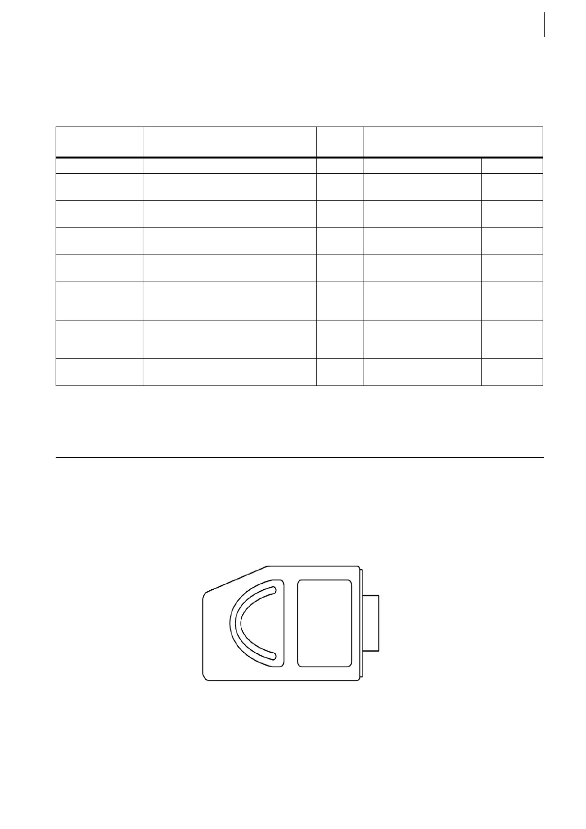
5.1 15 pin D-SUB plug for DIO
With one of this plug you can connect 4 digital input channels or 4 digital output
channels to an F-FEM-DDC or DDC Snap-in via soldering the wires to the solder
cups. The connector housings with quick-lock mechanism are included. With two
sets of 4 pieces each you can equip one DDC module.
Order number: please see Tab. 24.
Order Number Description Pieces
per set
Connections: what sensor to what
F-FEM?
TP08BB026A.01 15 pin D-SUB plug with solder cups 4 4 DI or 4 DO DDC
TP08BB027A.01 15 pin D-SUB plug with screw termi-
nals
4 4 DI or 4 DO DDC
TP08BB025A.01 Digital I/O connection box (DCB) 1 4 DI or 4 DO with M12
connectors
DDC
TP08BB028A.01 Counter Signal Adapter Connector
(CSA)
1 Diverse speed sensors,
1 or 2 tracks
DDC, CNT,
CON
TP08BB029A.01 Cable Adapter for CSA to
F-FEM-CNT or F-FEM-CON
1 CSA CNT, CON
TP08BB030A.01 Counter Signal Adapter Advanced
with cable to F-FEM-DDC
1 Universal built in unit with
versatile Schmitttrigger,
1 or 2 track
DDC
TP08BB031A.01 Counter Signal Adapter Advanced
with cable to F-FEM-CON or -CNT
1 Universal built in unit with
versatile Schmitttrigger,
1 or 2 track
CNT,CON
Not available
from AVL
Valve connectors – 1 DO DDC
Tab. 24
Fig. 33
 Loading...

