Operation
54
F-FEM-DDC — User’s Guide
4.8.6
Power Supply X17, X18
The two jacks are internally connected with the same pinout to make a
cascading of the power supply possible.
One plug then acts as an input, the other as an output. Up to three modules can
be connected in series with this kind of cabling. Therefore the "Power cable
module-to-module" is required as described in chapter Power Cable Module to
Module on page 23.
4.8.7
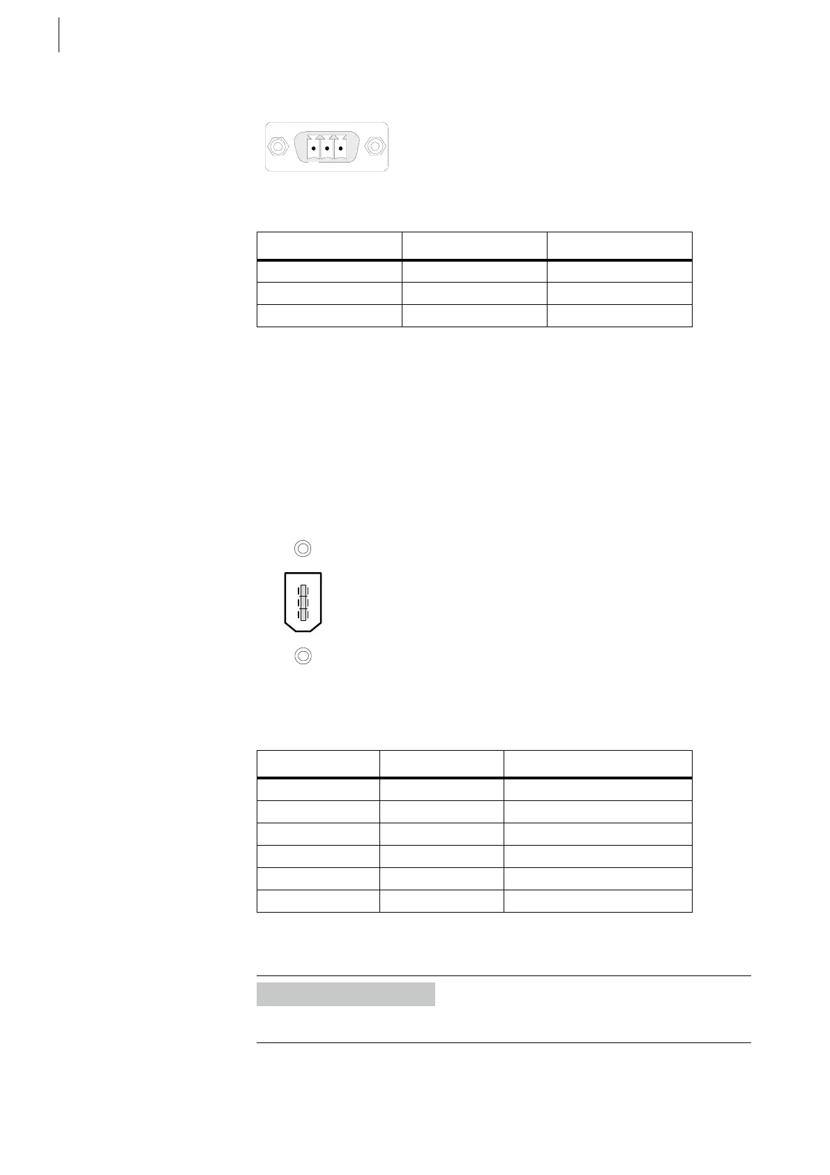
IEEE1394 X19, X20, X21
Pin assignment for X19, X20, X21:
All 3 sockets are equal. There is no priorization or dedicated input/output.
Fig. 30
Pin Signal Description
1GND 24 VGround
2 PE Prot. earth
3+ 24 V+ Power supply
Tab. 21
Fig. 31
Pin Signal Description
1+24 V
2 GND Ground
3 TPB_NEG
4 TPB_POS
5TPA_NEG
6TPA_POS
Tab. 22
Information
At this connector only prefabricated cables may be used.
 Loading...

