65
Options
F-FEM-DDC — User’s Guide
5.4.1
Assembling
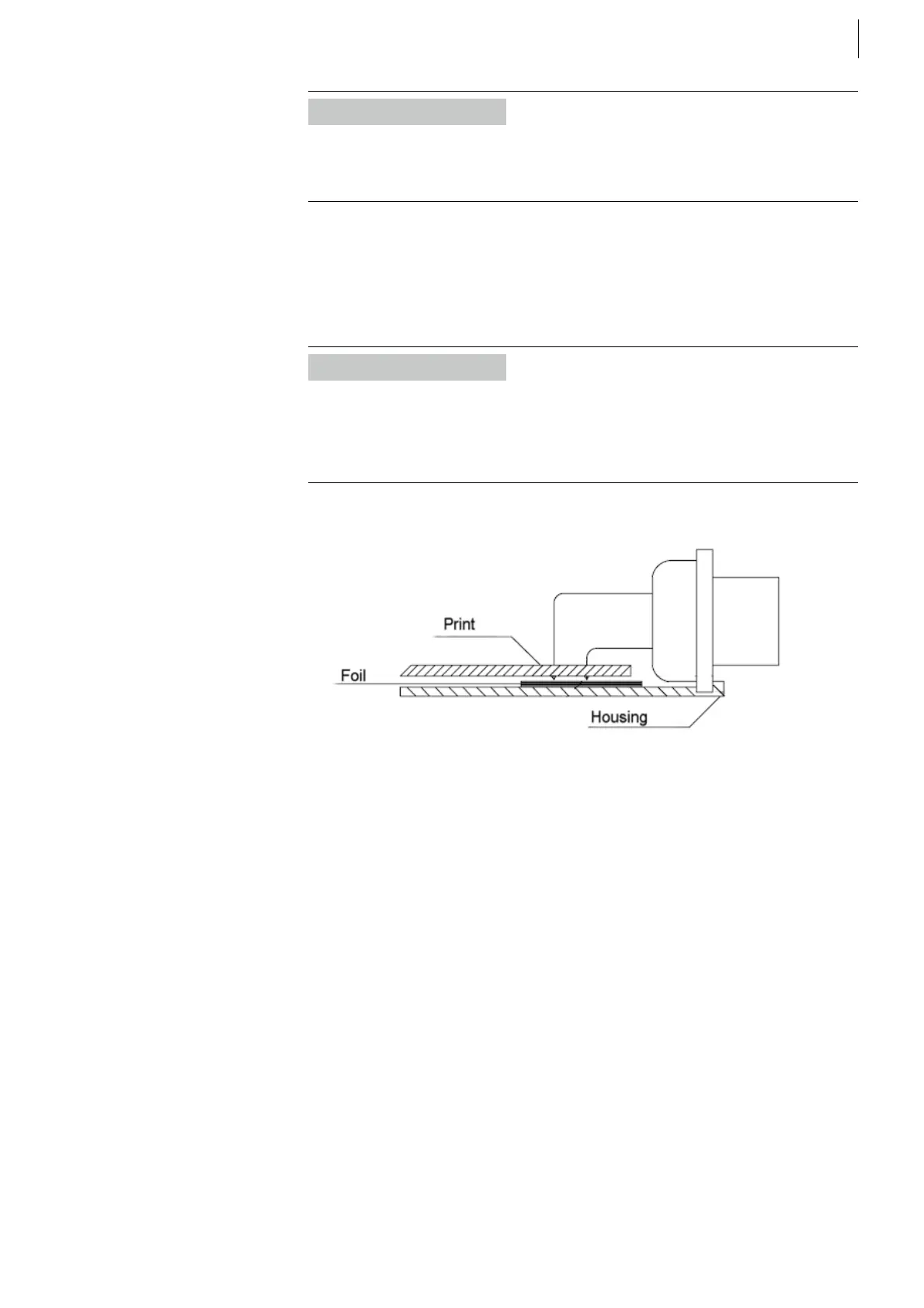
After connecting the sensor cable, the printed circuit board (Print) must be
assembled into the connector housing
Side view of the CSA connector:
Information
The maximum cross section of a wire connected to the screw terminals is limited
to 1.5 mm² inflexible or 1.0 mm² flexible with conductor sleeve (equivalent to
minimum AWG 15 or AWG 17 respectively).
Information
Please take care that the isolation foil is located between the connector housing
and the print to prevent a short circuit!
The PE wire (Fig. 42 on page 64) must be connected with the cable shield and
tightened with the strain-relief to the connector housing.
Fig. 43
 Loading...

