67
Options
F-FEM-DDC — User’s Guide
5.4.3
Specification
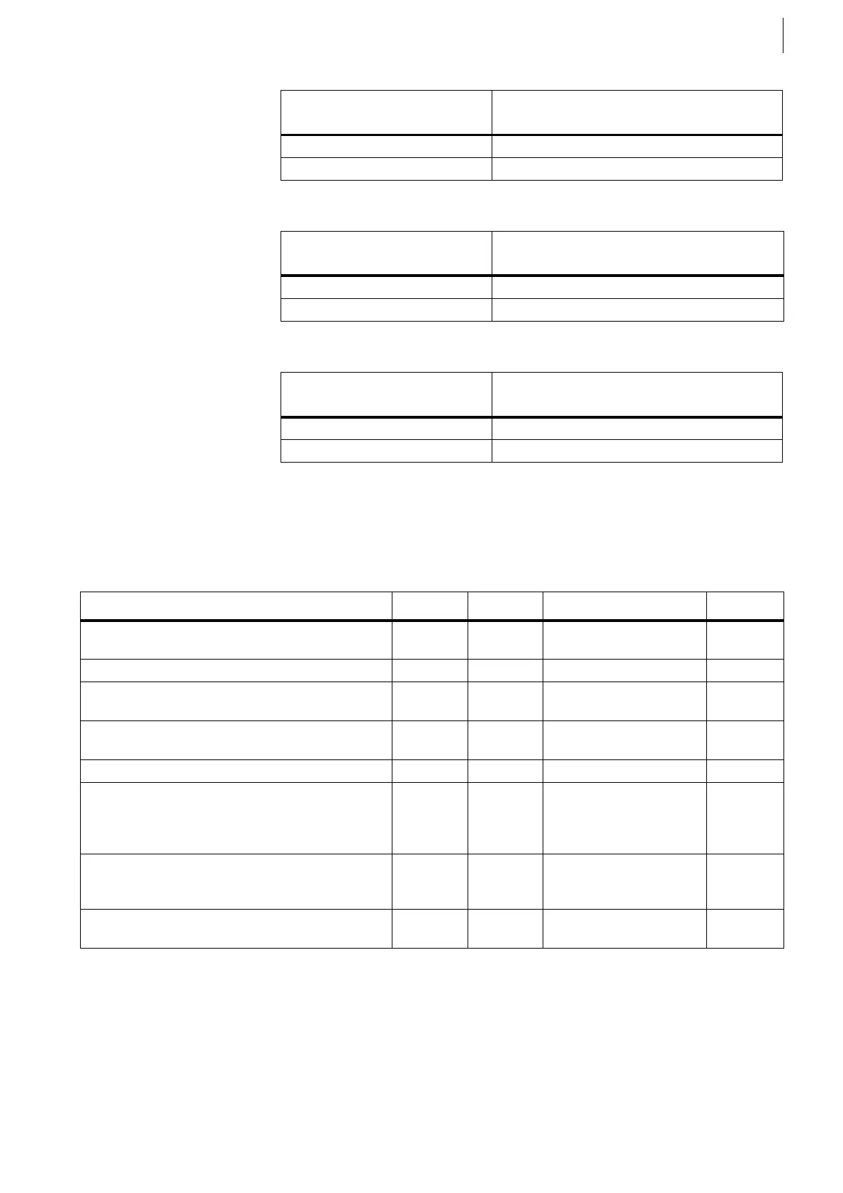
Counter Signal Adapter Specification:
*1) Typically the internal supply is used, see the usage of the DIP-switches.
*2) The voltage levels can be adjusted in various ways. Please see the chapter
Connecting an analog Sensor and using a variable Threshold on page 73.
SW1
(RS422 line termination)
Meaning
Open No line termination
Close RC termination active
Tab. 28
SW2
(Gain of Track-input)
Meaning
Open Gain = 1 (no amplification)
Close Gain = 2
Tab. 29
SW3
(Adapter and Sensor Supply)
Meaning
Open Connect an external supply of 5 ...30 V
Close Internal 24 V
supply
is used
Tab. 30
Measured quantity Min. Typical Max. Unit
Operating voltage for
external supply *1)
52430 V
DC
Power consumption from external supply 1.5 W
Differential Voltage
between every Pins, except 24 V and GND
100 V
DC
Output current on pin 5 for Sensor supply
(short circuit protected)
2A
Frequency 0 500 kHz
Threshold Voltage *2)
respected to GND
V
ON
V
OFF
1.35
1.00
9.55
8
Supply Voltage -2
Supply Voltage -2.35
V
V
V
HYST
(Hysteresis)
V
ON
- V
OFF
(depending on Freq.)
0.1 0.35 0.7 V
Input resistance
Within ± Supply Voltage
1MΩ
Tab. 31
 Loading...

