Options
68
F-FEM-DDC — User’s Guide
The following graphs shows the transfer characteristic of the speed sensor
adapter with different connections:
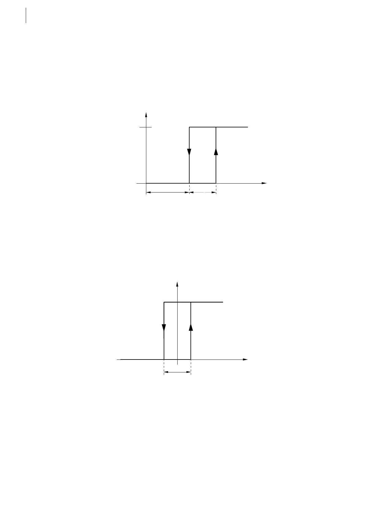
Single ended connection (Track+ signal respected to GND).
The Track-Input can act as a variable threshold input to accommodate to
different sensors depending on your requirements.
Transfer characteristic of Track+ to GND vs. output voltage:
The Hysteresis Voltage V
HYST
is fixed (see specification Tab. 30 on page 67).
Differential connection (Track+ respected to Track–)
Transfer characteristic of Track+ to Track- vs. output voltage:
Fig. 45
Fig. 46
U
out
logic 1
V
OFF
logic 0
Track-
U
V
ON
HYST
V
U
out
logic 1
V
OFF
logic 0
V
ON
Track +
U
Track -
U-
HYST
V
 Loading...

