39
Operation
F-FEM-DDC — User’s Guide
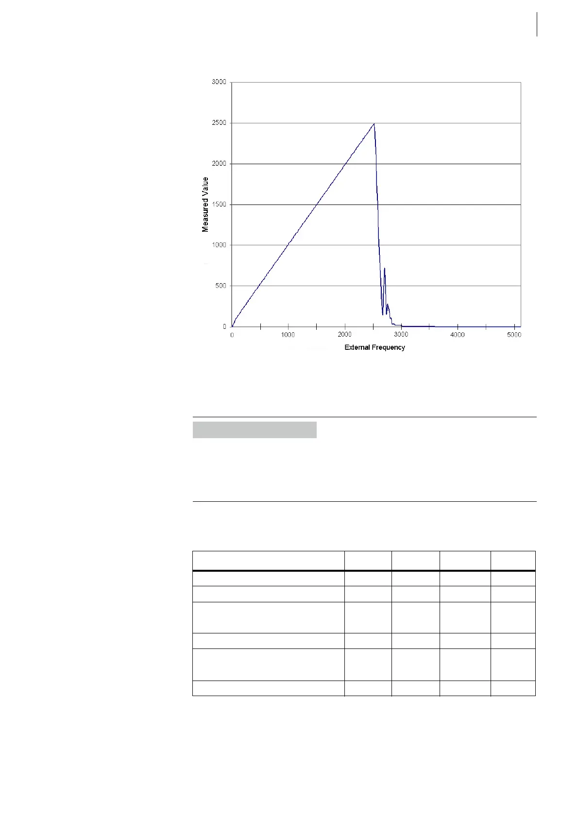
The filter response is shown in Fig. 17:
4.3.3
Specification
For electrical specification please see Tab. 9 on page 36 above.
Counter Input specification:
*) The minimum pulse width can be increased with a digital filter by parameter-
ization (depending on the PUMA Open Version) to eliminate spikes that are
coming from ringing signals, retriggering, or mismatched line impedances.
Fig. 17
Information
From PUMA Open version 1.5 onward, it is checked, whether the input values
are within the specified range. You find the valid ranges in the F-FEM Parameter-
ization manual.
Make sure that the adjustment- and calibration points are within the valid ranges!
Measured quantity Min. Typical Max. Unit
Signal slew rate 20 V/ms
Pulse width for CNT function *) 1.0 μs
Input frequency for CNT function
with Duty cycle 50:50
500 kHz
Resolution of reference clock 20 ns
Accuracy of reference clock
at 0 ...60 °C
± 25 ppm
Error at 20.000 rpm 0.8 rpm
Tab. 10
 Loading...

