59
Options
F-FEM-DDC — User’s Guide
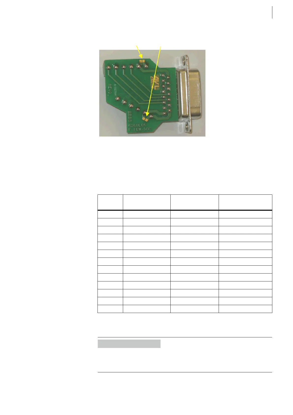
Bottom view with solder bridges.
Solder bridges for 24 V and GND_24:
Depending on the connected signals (inputs or outputs) you must use the pinout
of the connected socket, where you want to plug it.
Tab. 25 shows a summary of the pinouts for X41-X44, X51-X55 that are shown
in Tab. 13 on page 46, Tab. 15 on page 47 and Tab. 16 on page 50 before.
Pin assignments of screw terminals:
Fig. 36
Pin Signal at X41-X44
Digital Input
Signal at X51-X52
Dig. Out Relay
Signal at X53-X54
Dig. Out Transistor
1 +24 V out +24 V out +24 V out
3Ch1 NC
4Ch2 NC
5Ch3 NC
6Ch4 NC
8 GND_24 out GND_24 out GND_24 out
9 COMM COMM+
10 Ch1 + in Ch1 NO Ch1 + out
11 Ch2 + in Ch2 NO Ch2 + out
12 Ch3 + in Ch3 NO Ch3 + out
13 Ch4 + in Ch4 NO Ch4 + out
15 COMM– COMM–
Case Shield Shield Shield
Tab. 25
Information
The maximum cross section of a wire connected to the screw terminals is limited
to 1.5 mm² inflexible or 1.0 mm² flexible with conductor sleeve (equivalent to
minimum AWG 15 or AWG 17 respectively).
 Loading...

