Options
62
F-FEM-DDC — User’s Guide
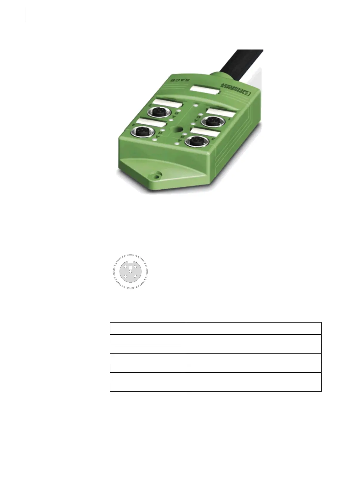
Digital Connection Box top view:
The channels are marked with 1 … 4, the LED for A shows the normal open
contact (NO), the LED for B shows the normal close contact (NC)
Pin assignment M12 connector AB-coded:
The names in brackets are according to the standard M12 naming convention
Fig. 39
Fig. 40
Pin Signal at M12 Connector
1 +24 V
2 Normal closed (B)
3GND
4 Normal open (A)
5PE
Case Shield
Tab. 26
 Loading...

