© AXION TECHNOLOGIES LTD. INSTALLATION
2. INSTALLATION
2.1. MECHANICAL INSTALLATION
This section explains how to install the components of the sign system. Failure to adhere to
the proper installation procedures may translate into high repair costs due to breakage
or failures and voids the warranty. Only skilled technicians should install this system. All
the precautions mentioned in this manual must be followed and all safety regulations of the
vehicle OEM and/or your Transit Authority must be adhered to.
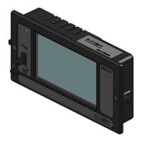
2.1.1. CONTROL CONSOLE / OSCP INSTALLATION
The Control Unit is the interface between the operator and the EDSS. It must be positioned in
a location easily accessible and readable without creating a nuisance for the operator. The
Control Unit has been designed for recessed installation. It is necessary to cut a hole on a
flat surface at the selected location (See Section 6.8). Follow all precautionary measures
mentioned in this manual and adhere to all safety regulations of the vehicle OEM and/or your
Transit Authority.
2.1.2. INTERIOR SIGNS INSTALLATION
The signs must be installed as per the following recommendations depending on their
location:
● The Front Destination Sign is located in the compartment above the operator cab
and facing outside.
● The Curb Side Sign is located inside the vehicle, on the first curb side window (right
side of the vehicle), facing outside, and adjacent to the door.
● The Route Side Sign is located inside the vehicle, on the first route side window (left
side of the vehicle).
● The Key Number Sign is located on the dashboard of the vehicle, facing outside. It
is positioned on the right side of the vehicle to do not interfere with the field of view of
the bus driver.
No matter the sign, it needs to be positioned as close as possible to the compartment window
(between 6 mm (¼") and 50 mm (2") for optimum performance. It may be vertically
positioned or inclined by 10° maximum towards the ground. It must remain accessible from
inside of the vehicle for maintenance. When installing, ensure:
● That display messages are fully visible from outside of the vehicle.
● To use mounting brackets matching those recommended for installation on a specific
type of vehicle.
● That power cables connected to signs are properly secured to prevent stress on
connector pins.
● To follow all precautionary measures mentioned in this manual and to adhere to all
safety regulations of the vehicle OEM and/or your Transit Authority.
User Manual (Revision A) Document No.: 3042145 Page 6
 Loading...