Home
Axion
Control Unit
40 Series
Axion 40 Series User Manual
4
of 1
of 1 rating
87 pages
Give review
Manual
Specs
To Next Page
To Next Page
To Previous Page
To Previous Page
Loading...
© AXION TECHNOLOGIES LTD.
TROUBLESHOOTING
5.4.
EDSS L
EDs DEFINITI
ON
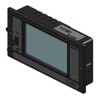
5.4.1.
CONTROL CONSOLE LED
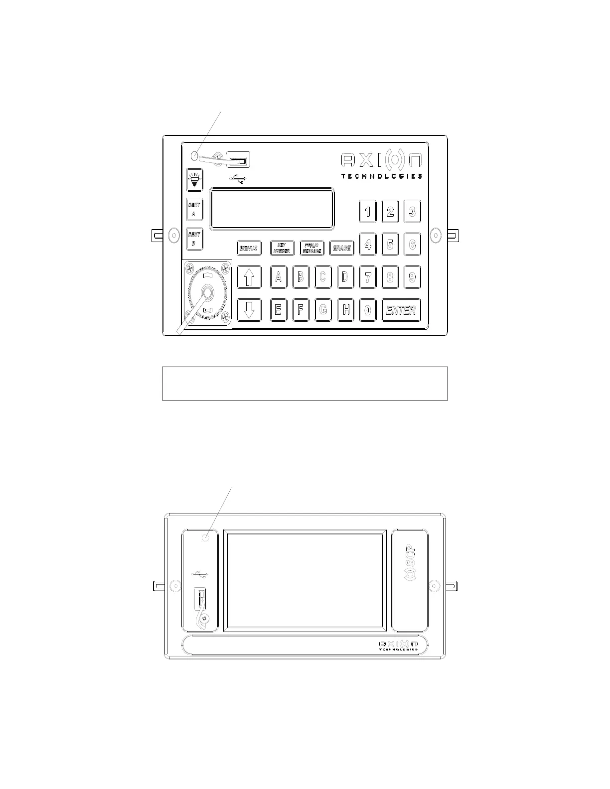
5.4.2.
OSCP LED
User Manual (Revision
A)
Document No.: 3042145
Page 58
LED / DEL
GREEN / VERT
OK
LED / DEL
RED / ROUGE
FAULT / ERREUR
Figure 38: Control Console
LED
DEL
Figure 39: OSCP LED
DEL
68
70
Table of Contents
Default Chapter
6
Table of Contents
6
1 Introduction
13
General
13
Features
13
Control Console / Oscp
13
Destination Sign
13
The 8.5-Inch Character Sign
13
The 8-Inch Character Sign
13
The 6-Inch Character Sign
14
The 4.5-Inch Character Sign
14
The 3.2-Inch Character Sign
14
Database Transfer
14
Data Transit Software
14
Transfer Unit (Tu)
14
Table 1: Database Transfer
14
Distress Signal
15
Yield" Signal
15
2 Installation
17
Mechanical Installation
17
Control Console / Oscp Installation
17
Interior Signs Installation
17
Outside Rear Sign Installation
18
Distress Signal Switch Installation
18
Yield Switch Installation
18
Electrical Interconnection
18
Main Power Cable
19
Figure 1: System Components Interconnection and Location
19
Acc Wire
20
Batt+ Wire
20
Gnd Wire
20
Ign Wire
20
Control Console Power Cable
20
Figure 2: Main Power Cable Connection
20
Figure 3: Control Console Cable Connection
21
Figure 4: Distress Switch Connection
22
Figure 5: Yield Switch Connection
22
Oscp Power Cable
23
Figure 6: Oscp Power Cable Connection
23
Figure 7: Distress Switch Connection
23
Figure 8: Yield Switch Connection
24
Oscp Communication Cable
25
Figure 9: Oscp Communication Cable Connection
25
THE 802.11 B/G Wi-Fi MODULE ANTENNA CABLE for CONTROL CONSOLE
26
THE 802.11 B/G/N Wi-Fi MODULE ANTENNA CABLE for OSCP
26
Figure 10: Control Console: Wi-Fi Module - Antenna Cable Connection
26
Figure 11: Oscp: Wi-Fi Module - Antenna Cable Connection
26
Curb Side Sign Power Cable
27
Figure 12: Curb Side Sign Cable Connection
27
Route Side Sign Power Cable
28
Figure 13: Route Side Sign Cable Connection
28
Rear Sign Power Cable
29
Key Number Sign Power Cable
29
Figure 14: Rear Sign Cable Connection
29
Installation Final Checks
30
Control Console Post-Installation Functionality Test
30
Step 1 : Edss Startup
30
Figure 15: Key Number Sign Cable Connection
30
Step 2: Control Console Configuration
31
Step 3: Distress (Emergency) Switch Test (if Installed)
31
Step 4: Yield Switch Test (if Installed)
31
Step 5: off Delay Functionality Test
31
Step 6: Photosensor Light Intensity Control
31
Oscp Post-Installation Functionality Test
32
Step 1: Signs System Startup
32
Figure 16: Oscp Startup
32
Figure 17: Message Management
32
Step 2: Distress (Emergency) Switch Test (if Installed)
33
Step 3: Yield Switch Test (if Installed)
33
Step 4: Photosensor Light Intensity Control
33
Step 5: off Delay Functionality Test
33
3 Maintenance
35
Test Equipment
35
Cleaning
35
Fuse Replacement
35
Figure 18: Fuse Definition
36
4 Edss Operation
38
Control Units
38
Use of the Control Console
38
Introduction to the User Interface
38
Figure 19: Keypad Definition
38
Table 2: User Interface Definition
38
Startup of the Control Console
39
Figure 20: Example of Network Configuration
39
Entering a Route
40
Figure 21: Entering a Route (Example)
40
Figure 22: Route Display on the Lcd (Example)
40
Entering a Public Message
41
Figure 23: Entering a Public Message (Example)
41
Figure 24: Displaying a Pa on the Lcd
41
Entering Text for Key Number Sign
42
Figure 25: Entering Text for Key Number Sign (Example)
42
Program and Recall Route Using the Dest a and Dest Bkeybuttons
43
Using the Backlight Keybutton
43
Using the Erase Keybutton
43
Figure 26: Displaying Key Number on the Lcd (Example)
43
Using the Functions Available through the Menus Keybutton
44
Figure 27: Entering the Menus Password
44
Error Code Interpretation for Menu 13
51
Communication Error ("E" Symbol)
51
Line of Products Error ("G" Symbol)
51
Figure 28: Link Error
51
Figure 29: Line of Products Error
51
Table 3: Control Console Menu Definitions
51
Identity Error ("I" Symbol)
52
Database Incompatibility Error ("D" Symbol)
52
Figure 30: Identity Error
52
Figure 31: Database Incompatibility Error
52
Photosensor Error ("P" Symbol)
53
Operating Frequency Error ("C" Symbol)
53
Error Priority
53
Figure 32: Photosensor Error
53
Figure 33: Operating Frequency Error
53
Database Transfer
54
Ptu Transfer
54
Figure 34: Ptu Transfer
54
Usb Transfer
55
Figure 35: Programming Using the Ptu Procedure
55
Figure 36: Programming Using the Universal Serial Bus (Usb) Procedure
55
Wireless (Wi-Fi) Transfer
56
Database Transfer Status
56
Figure 37: Programming Using the Wireless Fidelity Procedure
56
Operator's System Control Panel (Oscp)
58
5 Troubleshooting
60
Fault Finding
60
Power Supply Problems
60
Console Unit Problems
60
Sign Problems
61
Interpretation of Error Messages Displayed on Control Console Lcd
62
Communication Error Message
62
Line of Products Error Message
62
Sign Identity Error Message
63
Sign Database Error Message
63
Photosensor Error Message
63
Sign Operating Frequency Error Message
64
Ptu Error Messages
64
General Error Messages
65
Interpretation of Error Messages Displayed on Oscp
66
Communication Error Message
66
Sign Identity Error Message
66
Sign Database Error Message
66
Photosensor Error Message
68
Sign Operating Frequency Error Message
68
EDSS Leds DEFINITION
69
Control Console Led
69
Oscp Led
69
Figure 38: Control Console Led
69
Figure 39: Oscp Led
69
LED-DRVR-PS-CPU BOARD Leds
70
Figure 40: Led-Drvr-Ps-Cpu Board Leds
70
LED-DRVR-PS BOARD Leds
71
Figure 41: Led-Drvr-Ps Board Leds
71
6 Drawings
73
Interconnection Diagram
73
Figure 42: Electrical Interconnection
73
Main Power Cable
74
Figure 43: Main Power Cable
74
Control Console Cable
75
CABLE W/O INVERTER and W/O J1708 and RS-232 CONNECTION
75
Figure 44: Cable W/O Inverter and W/O J1708 and Rs-232 Connection
75
Cable with Inverter and Yield
76
Figure 45: Cable with Inverter and Yield
76
Cable with Inverter and Yield and with J1708 and Rs-232 Connection
77
Figure 46: Cable with Inverter and Yield and with J1708 and Rs-232 Connection
77
Oscp Cable
78
Power Cable
78
Figure 47: Oscp Power Cable
78
Power Cable with Inverter and Rs-232 Communication
79
Figure 48: Oscp Power Cable (Inverter & Rs-232)
79
Communication Cable with J1708 and Rs-232
80
Figure 49: Oscp Communication Cable (J1708 & Rs-232)
80
Curb/Route Side Sign Cable
81
Figure 50: Curb/Route Side Sign Cable
81
Exterior Rear Number Sign Cable
82
Figure 51: Exterior Rear Sign Cable
82
Key Number Sign Cable
83
Figure 52: Key Number Sign Cable
83
Control Console and Oscp Cutout Size
84
Outside Rear Sign Cutout Size
84
7 Reference Tables
86
Sign Identification Codes
86
Table 4: Sign Identification Code
86
Edss Fuse Table
87
Table 5: Fuse Value According to Sign Model
87
4
Based on 1 rating
Ask a question
Give review
Questions and Answers:
Need help?
Do you have a question about the Axion 40 Series and is the answer not in the manual?
Ask a question
Axion 40 Series Specifications
General
Brand
Axion
Model
40 Series
Category
Control Unit
Language
English