© AXION TECHNOLOGIES LTD. INSTALLATION
NOTE
Main power cable is supplied by the bus manufacturer. This cable must meet
the specifications in the following paragraphs.
2.2.1.1. BATT+ Wire
The BATT+ wire is typically connected to the battery through a circuit breaker or fuse capable
of withstanding the power requirements of your system configuration (see Table 5: Fuse
Value According to Sign Model, Section 7.2) This power source is always live on the system.
The BATT+ wire is connected to the power connector located on the Back Plate of the Front
Destination Sign. The minimum rating of this wire is 12 AWG.
2.2.1.2. GND Wire
The GND wire must be connected to the vehicle mass. The GND wire is connected to the
power connector located on the Back Plate of the Front Destination Sign. The minimum
rating of this wire is 12 AWG.
2.2.1.3. IGN Wire
The IGN wire must be connected to a 9-36 Vdc source that is activated when the Master
Coach Run Switch of the vehicle is turned on. The power signal is supplied by the Master
Coach Run Switch in all of its positions except for “OFF” and commands the Control Unit to
turn the EDSS on. The IGN wire is connected to the power connector located on the Back
Plate of the Front Destination Sign. The minimum rating of this wire is 18 AWG.
2.2.1.4. ACC Wire
The ACC wire is optional. When used, it must be connected to a 9-36 Vdc source activated
by a device other than the Master Coach Run Switch of the vehicle. The supplied power
signal commands the Control Unit to turn the EDSS on. The ACC wire is connected to the
ACC screw of the terminal block located on the Back Plate of the Front Destination Sign using
a #10 Ring Tongue terminal lug. The minimum rating of this wire is 18 AWG.
2.2.2. CONTROL CONSOLE POWER CABLE
User Manual (Revision A) Document No.: 3042145 Page 9
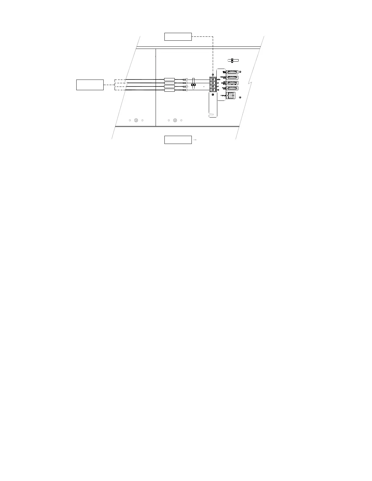
Figure 2: Main Power Cable Connection
BUS POWER
ALIMENTATION DE
L' AUTOBUS
FRONT SIGN RIGHT BACK PLATE
PLAQUE DE DROITE AFFICHEUR AVANT
OPTIONAL
FACULTATIF
GND
ACC
IGN
BATT+
TERMINAL BLOCK
BORNIER À VIS
 Loading...