© AXION TECHNOLOGIES LTD. INSTALLATION
The Control Console power cable connects the Console to the sign junction and other bus
communication networks, if required. Also, this cable can connect the Distress Signal switch
to the Control Console. There are various types of the power cable. The figures in Section
6.3 CONTROL CONSOLE CABLE show the different types of cables that can be used.
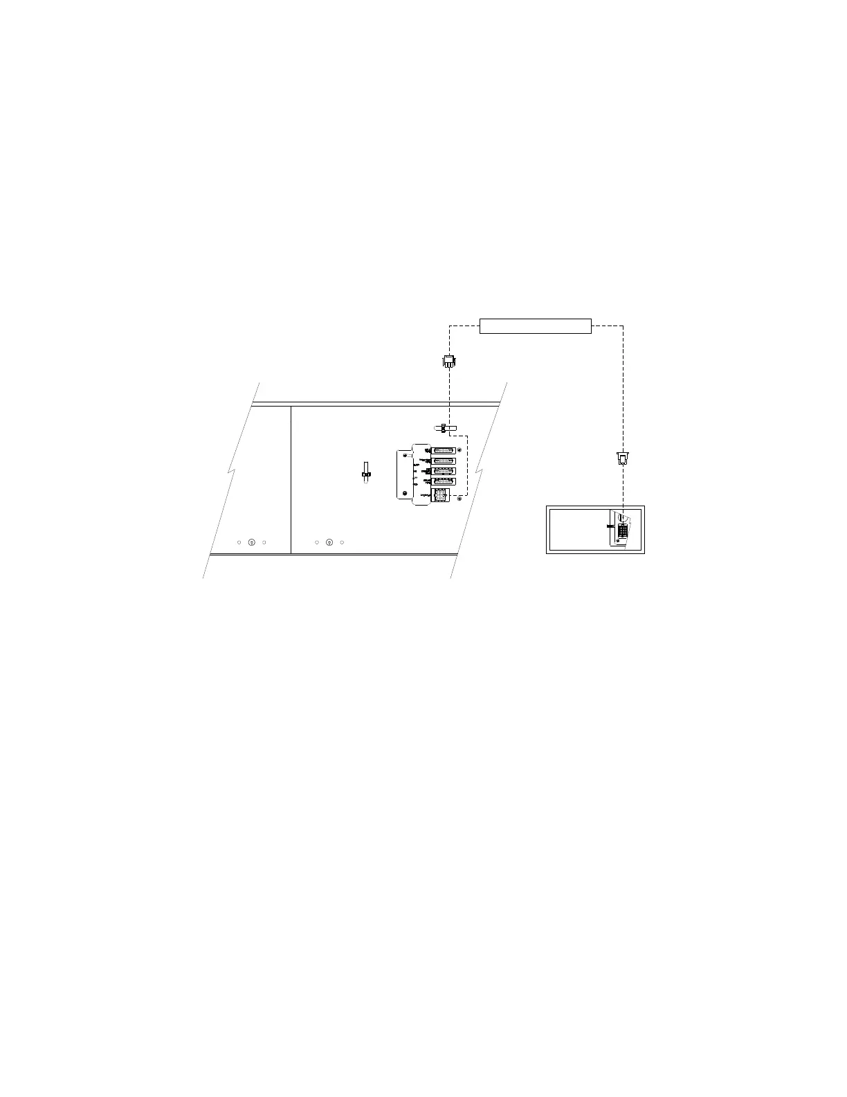
The Control Console power cable connects as follows:
● Connect the Control Console extension cable (9-pin connector) to the CONSOLE
connector (9-pin connector) located on the Back Plate of the Front Destination Sign.
(See Figure 3)
● Connect the other end of the Control Console extension cable (12-pin connector) to
the corresponding connector located on the Control Console. (See Figure 3).
● Connect the distress signal switch wire to the bus distress switch. (See Figure 4).
● If the Control Console power cable used is the one shown in Section 6.3.1, the
power signal supplied by the distress switch must be a ground signal (GND).
● If the Control Console power cable used is the one shown in Sections 6.3.2 and
6.3.3, the power signal supplied by the distress switch must be a 9-36 Vdc signal.
● The distress switch is supplied and installed by the bus manufacturer.
User Manual (Revision A) Document No.: 3042145 Page 10
Figure 3: Control Console Cable Connection
CONTROL CONSOLE POWER CABLE
CÂBLE D' ALIM. CONSOLE DE COMMANDE
FRONT SIGN RIGHT BACK PLATE
PLAQUE DE DROITE AFFICHEUR AVANT
CONTROL CONSOLE
CONSOLE
DE COMMANDE
 Loading...