© AXION TECHNOLOGIES LTD. INSTALLATION
2.3. INSTALLATION FINAL CHECKS
Ensure that all components of the EDSS are properly attached mechanically and well secured
to the bus structure. They should not interfere with the other systems of the vehicle nor
should they be damaged by them. Close all access panels when finished.
2.4. CONTROL CONSOLE POST-INSTALLATION FUNCTIONALITY TEST
This section presents the information required to start up the EDSS and check functionality of
each of its components fit with a control console.
2.4.1. STEP 1 : EDSS STARTUP
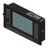
First, the Control Console displays the following information at startup:
AXION
OPTION NO: xxx
where “xxx” is the sign option number.
Second, the control Console displays the system configuration as follows:
FT: xx SD: xx RR: xx
RS: xx KN: xx NS: xx
where “xx” is the ID of the signs configured in the Control Console. At the first startup, there
is no sign configured. The Control Console displays the following text.
CONFIG. NOT DEFINED
PRESS ANY KEY
Press Enter. The Control Console verifies the config present on the bus prior to continuing.
Finally, the Control Console starts the test mode and displays the following information:
User Manual (Revision A) Document No.: 3042145 Page 19
Figure 15: Key Number Sign Cable Connection
KEY NUMBER SIGN
AFFICHEUR
NUMÉRO DE POSTE
KEY NUMBER SIGN POWER CABLE
CÂBLE D' ALIMENTATION AFF. # POSTE
FRONT SIGN RIGHT BACK PLATE
PLAQUE DE DROITE AFFICHEUR AVANT

 Loading...