© AXION TECHNOLOGIES LTD. INSTALLATION
2.2.3. OSCP POWER CABLE
The OSCP power cable connects the OSCP to the front sign junction. Also, this cable can
connect the Distress Signal switch to the OSCP. There are various types of the power cable.
The figures in Section 6.4 OSCP CABLE show the different types of cables that can be used.
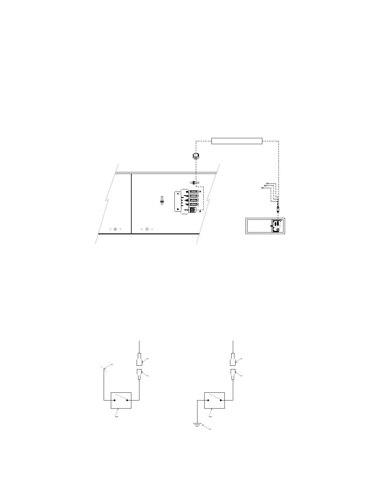
The OSCP power cable connects as follows:
● Connect the OSCP extension cable (9-pin connector) to the OSCP connector (9-pin
connector) located on the Back Plate of the Front Destination Sign. (See Figure 6)
● Connect the other end of the OSCP extension cable (D-sub 15-pin connector) to the
corresponding connector located on the OSCP. (See Figure 6).
● Connect the distress signal switch wire to the bus distress switch. (See Figure 7).
● If the OSCP Power cable used is the one shown in Section 6.4.2, the power
signal supplied by the distress switch must be a ground signal (GND).
● If the OSCP power cable used is the one shown in Sections 6.4.1, the power
signal supplied by the distress switch must be a 9-36 Vdc signal.
● The distress switch is supplied and installed by the bus manufacturer.
User Manual (Revision A) Document No.: 3042145 Page 12
Figure 6: OSCP Power Cable Connection
Figure 7: Distress Switch Connection
"PANDUIT" (DNF18-250FIB)
EMERGENCY SWITCH
CONTROL CONSOLE CABLE
QUICK CONNECT TERMINAL
INTERRUPTEUR D'URGENCE
EMERGENCY SWITCH
"PANDUIT" (DNF18-250FIB)
QUICK CONNECT TERMINAL
TERMINAL "QUICK CONNECT"
CABLE CONSOLE DE COMMANDE
CONTROL CONSOLE CABLE
MISE A LA TERRE DE L'AUTOBUS
BUS GROUND
TERMINAL "QUICK CONNECT"
INTERRUPTEUR D'URGENCE
CABLE CONSOLE DE COMMANDE
24 VOLTS
CONTROL CONSOL POWER CABLE
CÂBLE D' ALIM. AFF. CONSOLE DE COMMANDE
CONTROL UNIT
UNITÉ DE CONTROLE
OSCP
FRONT SIGN RIGHT BACK PLATE
PLAQUE DE DROITE AFFICHEUR AVANT
 Loading...