© AXION TECHNOLOGIES LTD. INSTALLATION
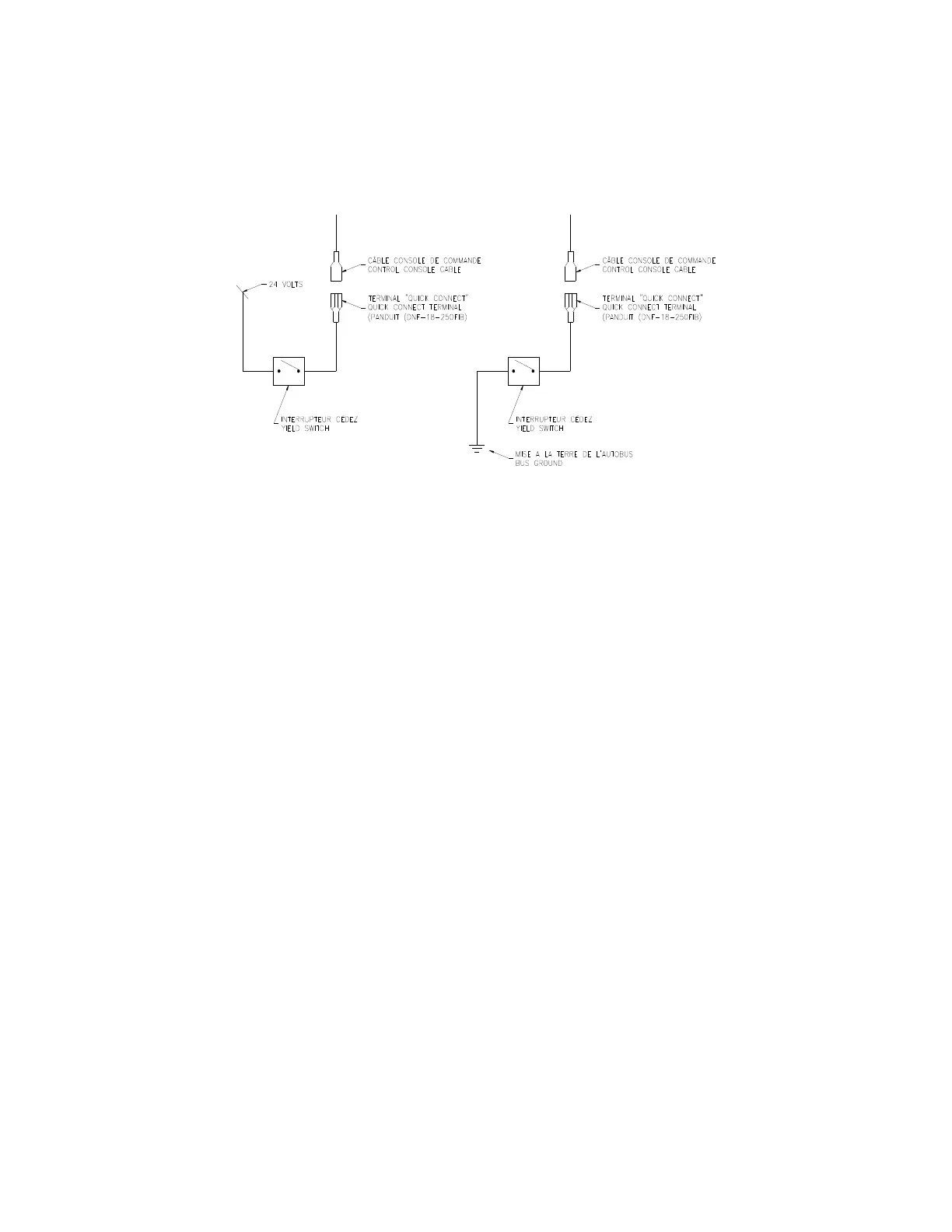
● Connect the yield signal switch wire to the bus yield switch. (See Figure 8).
● If the OSCP power cable used is the one shown in Sections 6.4.1, the power
signal supplied by the distress switch must be a 9-36 Vdc signal.
● The yield switch is supplied and installed by the bus manufacturer.
● If the cable used includes J1708-type connectors and/or RS-232-type connectors,
contact the Customer Service of Axion Technologies Ltd., to get more information on
how to connect these two connectors.
User Manual (Revision A) Document No.: 3042145 Page 13
Figure 8: Yield Switch Connection
 Loading...