▪ The MONITOR Tab’s TX and RX Columns:
• Port name - The matrix switch and port number that is being monitored.
• Src Name/Dst Name - The source/destination as named in the SMP2 configuration
• Portname - Functions being monitored on that port
• Model - Internal model number of the extender (if known).
• Serial - Serial number of the extender (if known).
• M1 - Enables Monitor 1 for this port. Right-click allows the entire column to be modified at once.
• M2 - Enables Monitor 2 for this port. Right-click allows the entire column to be modified at once.
• Hide - Allows the deselection of this port from being displayed.
• Valid Vid - Indicates a valid video signal at this port.
• Board Temp - Temperature of the extender board.
• FPGA Temp - Temperature of the extender FPGA.
• LS conn - Low speed connected.
• Coll - Collaboration enabled for this port.
• OOB - Out Of Band enabled.
• DDC - Indicates the DDC mode selected for the Tx extender.
• Int Ms - Indicates whether the Intuitive Mouse feature is enabled.
• L1 - Power level of L1.
• L2 - Power level of L2.
• L3 - Power level of L3.
• L4 - Power level of L4.
• L5 - Power level of L5.
• Alarm - Indicates an alarm condition reported from the extender. Left-click for details.
• Last Alarm - Indicates the date and time of the latest alarm condition. Left-click on an entry to
clear it. Right-click on the heading to clear all.
• Count - Number of packets received during the last scan.
• Time - Time of the last scan.
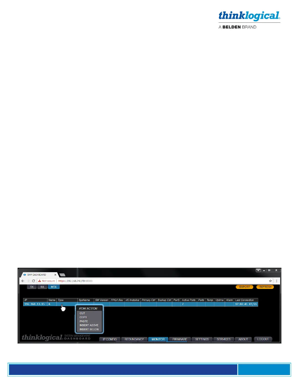
▪ The Matrix Switch (MTX) Tab
Additional Matrix Switches can be added or deleted by right-clicking a row and choosing from the drop-
down menu. Multiple Matrix Switches can be connected to each other with tie lines. (See the Tie Line
Tab, pg. 32.)