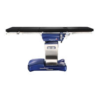
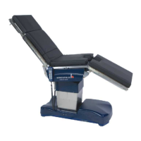
OPERON D 850 SURGICAL TABLE
TABLE OF CONTENTS
Rev. 1 700000120
S-4
TABLE OF CONTENTS CONTINUED
FOOTSWITCH (OPTIONAL) .................................................................................................... 2-7
PRINCIPLES
OF OPERATION 3-1
HYDRAULIC SYSTEM............................................................................................................... 3-1
Hydraulic Power Unit ............................................................................................................3-1
Hydraulic Manifolds .............................................................................................................. 3-1
Column Manifold................................................................................................................... 3-1
Floor Lock Manifold.............................................................................................................. 3-2
Floor Lock System...................................................................................................................... 3-2
MANIFOLD VALVE DESCRIPTION ........................................................................................ 3-3
Manifold Valve Operation ..................................................................................................... 3-4
COLUMN HYDRAULICS .......................................................................................................... 3-5
General Information............................................................................................................... 3-5
DETAILS
OF OPERATION 4-1
Height Up and Down.................................................................................................................. 4-1
Tilt Left and Right ...................................................................................................................... 4-1
Trendelenburg and Reverse Trendelenburg............................................................................... 4-1
Table Top Hydraulics................................................................................................................. 4-1
HOLLOW PLUGS AND SEALS................................................................................................. 4-3
Using Hollow Plugs and Washers to Secure Hydraulic Lines............................................... 4-4
Hollow Plug Torque Specifications ....................................................................................... 4-4
SERVICE 5-1
HYDRAULIC FLUID .................................................................................................................5-1
ELECTRONIC CONTROL SYSTEM.......................................................................................... 5-1
CPU........................................................................................................................................ 5-1
Communication Interface (RS232) Board ............................................................................. 5-1
Position Sensors and Switches............................................................................................... 5-1
Slide & Height Sensor ...........................................................................................................5-2
Auxiliary Pendant Switch ...................................................................................................... 5-2
Trend/Tilt Sensor ................................................................................................................... 5-3
Leg and Back Angle Sensors ................................................................................................. 5-3
Power Supply System ............................................................................................................ 5-3
Batteries ................................................................................................................................. 5-4
Power Input System ............................................................................................................... 5-5
CONTROL PENDANTS ............................................................................................................. 5-6
Primary Hand Pendant ........................................................................................................... 5-6
Auxiliary Hand Pendant......................................................................................................... 5-7
WIRING...................................................................................................................................... 5-7
MECHANICAL SLIDE SYSTEM................................................................................................ 5-7
U
SING THE SERVICE PROGRAM 6-2
Connect to the Table .................................................................................................................. 6-2
Launch the Service Program......................................................................................................6-2
The Hand Pendant Graphic.................................................................................................... 6-2
The Service Program Menus ...................................................................................................... 6-3
Buttons................................................................................................................................... 6-8
Device Settings Screen ..........................................................................................................6-8
Software Commands with Primary Pendant ....................................................................... 6-12
CPU Error Codes ................................................................................................................. 6-13
Table of Figures
Figure S-3 Serial Number and Regulatory Approval Labels....................................................S-12
Figure 1-1 OPERON D 850 Surgical Table ............................................................................... 1-1