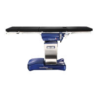
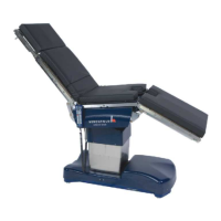
OPERON D 850 SURGICAL TABLE
TABLE OF CONTENTS
700000120 Rev. 1
S-5
Table of Figures continued
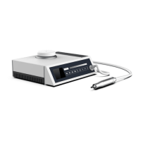
Figure 1-2 Power Center Components........................................................................................1-3
Figure 1-3 Primary Hand Pendant Indicators..............................................................................1-4
Figure 1-4 Primary Hand Pendant Functions..............................................................................1-5
Figure 1-5 Footswitch .................................................................................................................1-6
Figure 1-6 Deploying Foot Pump Pedal......................................................................................1-6
Figure 1-7 Emergency Switch.....................................................................................................1-7
Figure 1-8 Auxiliary Hand Pendant ............................................................................................1-7
Figure 2-1 Pinch Points...............................................................................................................2-1
Figure 2-2 Table Orientation.......................................................................................................2-2
Figure 2-4 Headrest.....................................................................................................................2-6
Figure 2-5 Leg Section Attachment ............................................................................................2-6
Figure 2-6 Assembled Leg Section .............................................................................................2-6
Figure 2-7 Footswitch .................................................................................................................2-7
Figure 3-1 Manifold Distribution Blocks....................................................................................3-1
Figure 3-2 Distribution Blocks ...................................................................................................3-1
Figure 3-3 Floor Lock Manifold .................................................................................................3-2
Figure 3-4 Location of Floor Lock Manifold In Base.................................................................3-2
Figure 3-5 Floor Lock System Operation ...................................................................................3-3
Figure 3-6 Manifold Valve .........................................................................................................3-4
Figure 3-7 Column Hydraulics ...................................................................................................3-6
Figure 4-1 Lift Column/Cylinders ..............................................................................................4-1
Figure 4-2 Tilt Cylinder ..............................................................................................................4-1
Figure 4-3 Hose Routing To Upper Frame .................................................................................4-2
Figure 4-4 Right Side Frame Cylinders ......................................................................................4-2
Figure 4-5 Back and Leg Cylinders ............................................................................................4-3
Figure 4-6 Left and Right Kidney Cylinder................................................................................4-3
Figure 4-7 Hollow Plugs and Washers........................................................................................4-4
Figure 4-8 Securing Hydraulic Line ...........................................................................................4-4
Figure 5-1 D 850 Reservoir ........................................................................................................5-1
Figure 5-2 Height Sensor ............................................................................................................5-2
Figure 5-3 Slide Sensor...............................................................................................................5-2
Figure 5-4 Auxiliary Pendant Switch..........................................................................................5-2
Figure 5-5 Kidney Switch ...........................................................................................................5-2
Figure 5-6 Trend/Tilt Sensor (viewed from under table)............................................................5-3
Figure 5-7 Leg & Back Section Proximity Sensors ....................................................................5-3
Figure 5-8 Power Supply System................................................................................................5-3
Figure 5-9 Charging circuit output diagram................................................................................5-4
Figure 5-10 Batteries.....................................................................................................................5-4
Figure 5-11 Terminal ....................................................................................................................5-5
Figure 5-12 Transformer...............................................................................................................5-5
Figure 5-13 Power Supply ............................................................................................................5-5
Figure 5-14 Power Input Center....................................................................................................5-6
Figure 5-15 Primary Hand Pendant...............................................................................................5-6
Figure 5-16 Slide Screw Drive Belt And Potentiometer Cable Routing.......................................5-7
Figure 6-1 RS232 Connection.....................................................................................................6-2
Figure 6-2 Login Form................................................................................................................6-2
Figure 6-3 Service Program Main Menu Screen.........................................................................6-1
Figure 6-4 Service Program Main Menu Screen Menu Options.................................................6-2
Figure 6-5 File Menu Options.....................................................................................................6-3
Figure 6-6 Windows File open Selection Screen........................................................................6-4
Figure 6-7 Save Settings to file...................................................................................................6-4
Figure 6-8 Device Settings Report..............................................................................................6-4