540
6
CONTROL STATION
Studio ti 03312 540-04usa
93
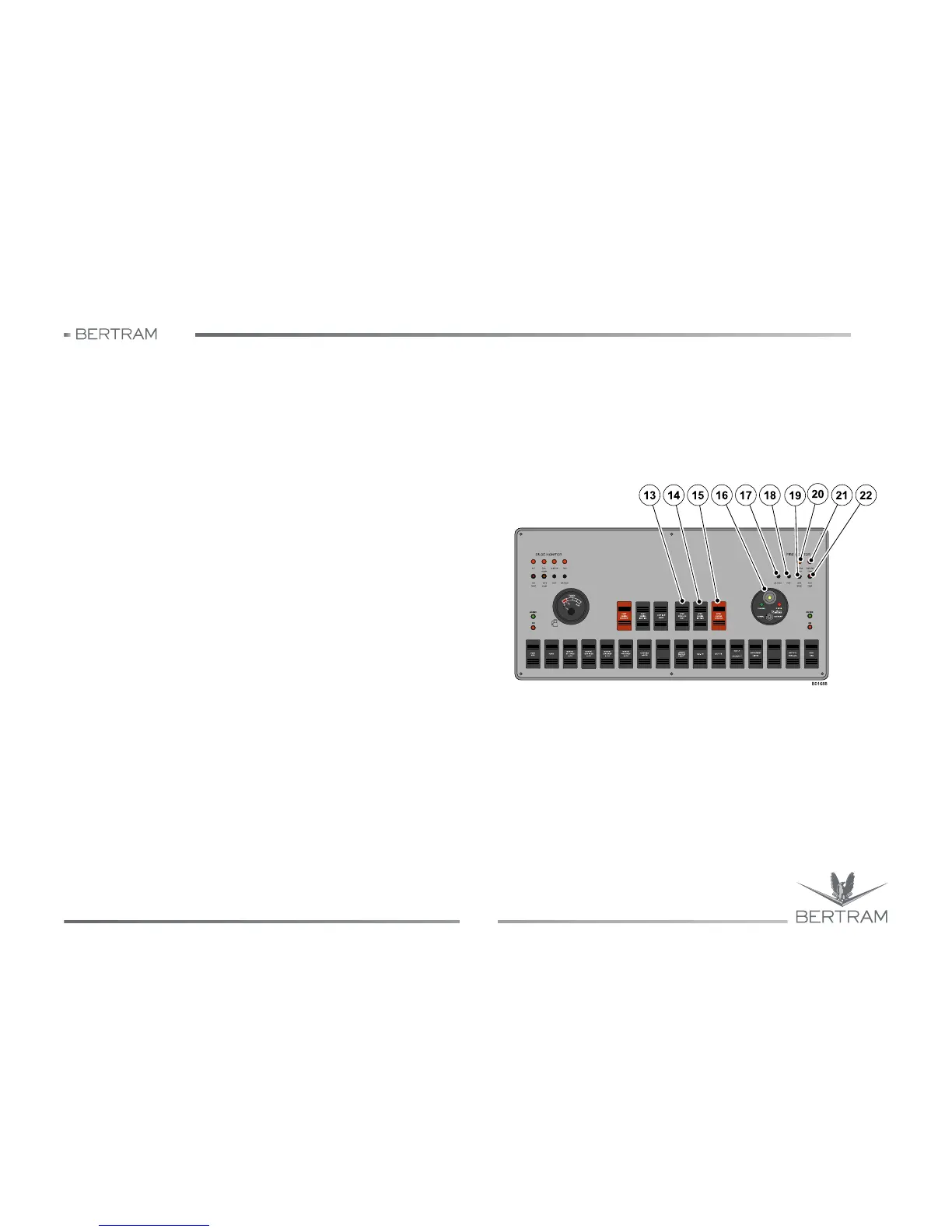
13. Engine synchronizer switch
This switch allows to activate the synchronization of both engines
and to use a one lever operation mode to control the engines.
14. Starboard ENGINE IGNITION switch
This switch allows to enable the start/stop of the starboard engine.
15. Starboard engine STOP/START switch
This switch enables to start/stop the starboard engine.
16. Fire-fighting alarm panel
This panel visualizes the warning lamps connected to the fire-fighting
system located in the engine room and it includes the OVERRIDE/
NORMAL switch.
17. Squelch button for firefighting alarm signal
This switch allows to disconnect the fire hazard signal buzzer.
18. Test button for high temperature signal
The test button is used to verify the correct operation of each signal
light of the panel. When using the test button, all LEDs must be ON
and the buzzer must sound to confirm the correct operation of the
signal system. When releasing the button all LEDs must go out and
the buzzer must clear off.
19. Starboard generator light
This light indicates that the starboard generator is running.
20. Generator room high temperature signal light
This light indicates that the temperature in the generator room is too
high.
21. Engineroom high temperature signal light
This light indicates that the temperature in the engineroom is too
high.
22. Starboard engine exhaust warning lamp
This light indicates high temperature inside of starboard engine
exhaust ducts.