8
1.2.1.2 BCS-COM rear panel detailed description
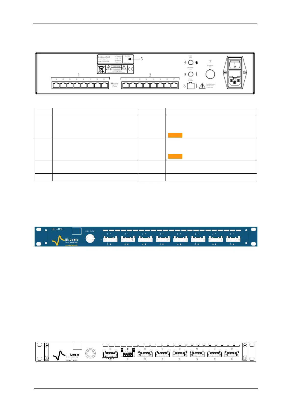
A description of the rear panel of the BCS communication module is given below:
Table 2 : Detailed BCS-COM rear panel description
Low Power Relay: Not available
Logical opto-coupler output (normal open con-
tact)
Caution: 150 mA – 100 VAC max
Power AC Relay: Not available
Opto-Triac Relay, used to connect bea-
con/flashing light alarm
Caution: 2 A - 250 VAC max
1.2.2 BCS-805 module
Each BCS-805 module is referred to a letter (from A to P). The letter is located in the left side
of the front panel (white square), above the Bio-Logic logo (Fig. 5).
Each BCS-805 module has 8 channels numbered from the left to right (1 to 8).
Fig. 5: BCS-805 front panel.
Each channel can be set, run, paused or stopped, independently of the others, using identi-
cal or different test protocols. Any setting of any channel can be modified during a run, with-
out the need to stop and restart the experiment. The channels can also be grouped and run
synchronously.
A CELL On/Off button is available on the front panel of the BCS-805 module. This button
enables or disables the power output of the 8 channels of the BCS-805 module, not the full
cabinet. If the button is off, all of the channels in the module are switched off.
On the rear panel a subD-9 pins connector is available with analog input/output and trigger
input/output (TTL level) (paragraph 1.2.3.3).
1.2.2.1 BCS-805 front panel detailed description
A scheme with detailed description of the front panel of the BCS-805 is given below.
Fig. 6: BCS-805 front panel detailed description.