BCS-8xx series installation manual
16
Table 9: Detailed front panel description.
10A Circuit Breaker for Power line
Module A
10A Circuit Breaker for Power line
Module B
10A Circuit Breaker for Power line
Module C
10A Circuit Breaker for Power line
Module D
10A Circuit Breaker for Power line
Module E
10A Circuit Breaker for Power line
Module F
10A Circuit Breaker for Power line
Module G
10A Circuit Breaker for Power line
Module H
Release QG1 breaker when Emer-
gency Stop Operation button is
pressed on the BCS-COM module.
Caution!:
For this function, Emergency Stop
connector (JC1F) should be connect-
ed to the BCS-COM with the appro-
priated cable
General incoming 3Phases 50A Cir-
cuit Breaker coupled with protection
30mA residual current device
Caution!: !:
release the emergency stop button
before initiating (re-arm)
General power line breaker on Indica-
tor
Logic line (UPS) breaker on Indicator
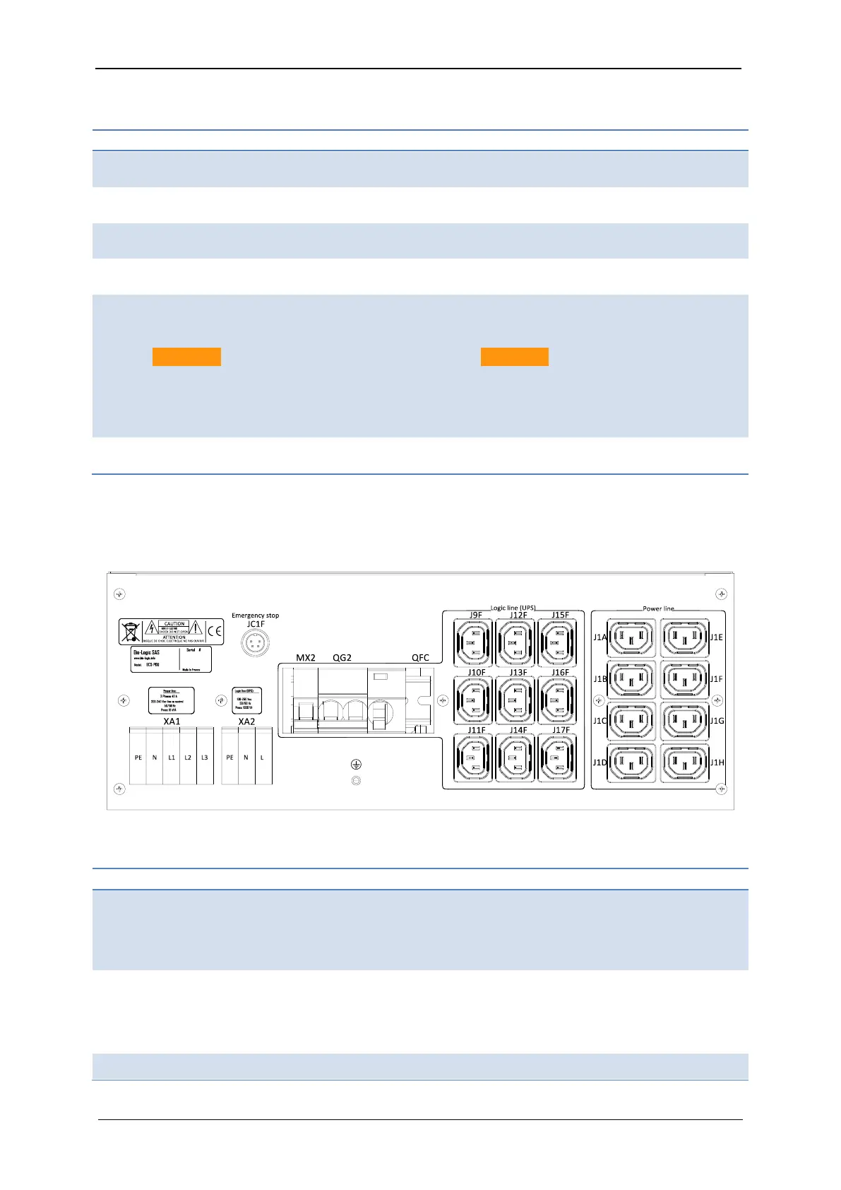
1.2.5.2 BCS-PDU rear panel detailed description
The three-phase power inputs as well as the power and logic line outputs are available in the
rear panel as described in the Fig. 17 and Table 10.
Fig. 17: BCS-PDU rear panel.
Table 10: Detailed rear panel description.
Power Line VAC input
For more information, refer to the
BCS-PDU electrical connections
chapter
Logic Line VAC input
For more information, refer to the
BCS-PDU electrical connections
chapter
Optional Stop operation Command
(can be added on request to release
QG2 on the Emergency Stop Button
of the BCS-COM module)
Logic Line 10A Circuit Breaker
(coupled with 30mA residual current
device protection)
4A Circuit Breaker protection for Stop
Stop of Operation connector (should