12
or at the end of the experiment. It is used to start or stop an experiment on another
instrument.
The Trigger signals have high and low levels:
+ 3.5 V < Trigger high level < + 5 V
0 V < Trigger low level < 0.8 V
+5V and -5V are DC voltages with an amplitude of 5V. These connectors can be
used to power an external device using a maximum current of 20 mA.
Ground is tied to the earth.
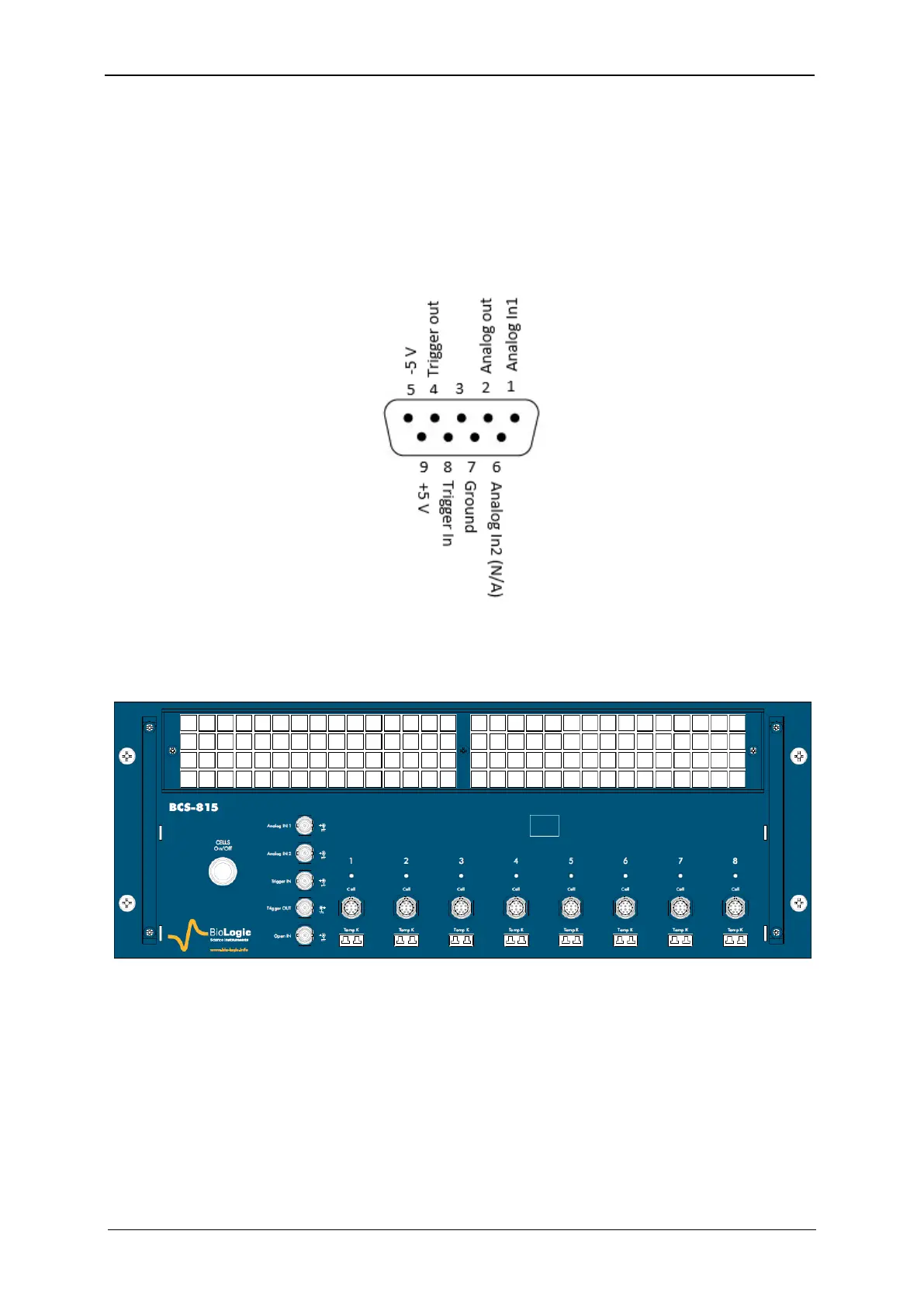
Fig. 10: Structure of the DB9 connector.
1.2.4 BCS-815 module
Figure 11 below shows the front panel of the BCS-815 module.
Fig. 11: BCS-815 front panel.
Each BCS-815 module is equipped, with one Analogic IN, one Analogic OUT, one Trigger IN,
one Trigger OUT and one Open IN connections. These connections are shared between the
8 channels of the BCS-815.
Every channel of the BCS-815 is equipped with a K-type thermocouple connection for moni-
toring cell temperature on that particular channel.
A CELL On/Off button is available on the front panel of the BCS-815 module. This button
enables or disables the power output of the 8 channels of the BCS-815 module, not the full
cabinet. If the button is off, all of the channels in the module are switched off.