BCS-8xx series installation manual
14
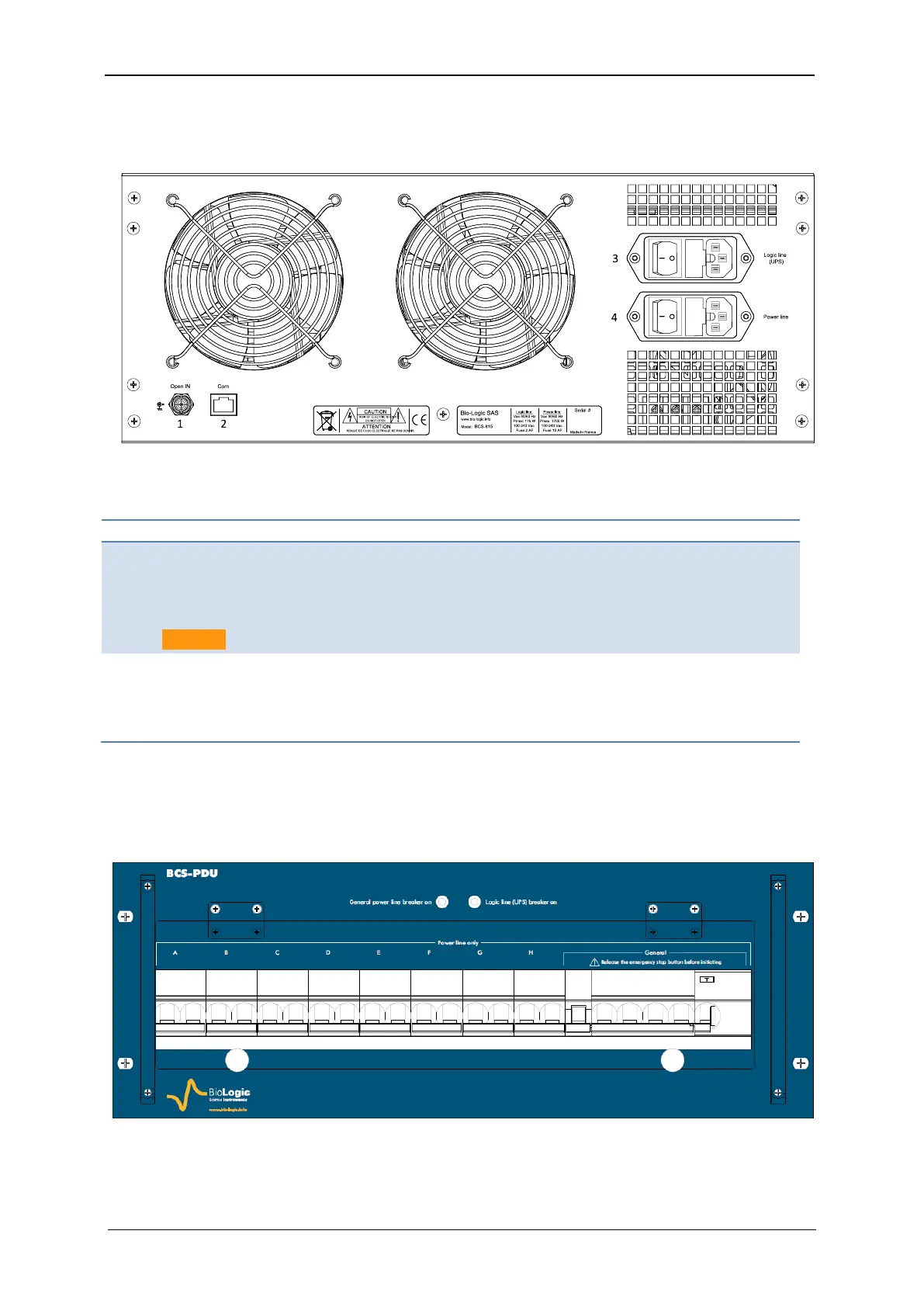
1.2.4.2 BCS-815 rear panel detailed description
Table 8: Detailed BCS-815 rear panel description.
Open IN:
Open relays of all the channels
when contact closed or logical
zero input (TTL level)
Caution: 5.75VAC max!
Com:
Communication input, should be con-
nected to the BCS-COM (refer to the
appropriate module letter)
Logic Line:
Power entry module (IEC320
C13 + fuses + switch on/off) for
logic control part
Power Line:
Power entry module (IEC320 C13 +
fuses + switch on/off) for power control
part.
1.2.5 BCS-PDU module
A power distribution unit module can be provided with BCSC-38U and BCSC-24U cabinets
for BCS configuration with more than two BCS-815 modules.
Fig. 13: BCS-PDU front panel.