10
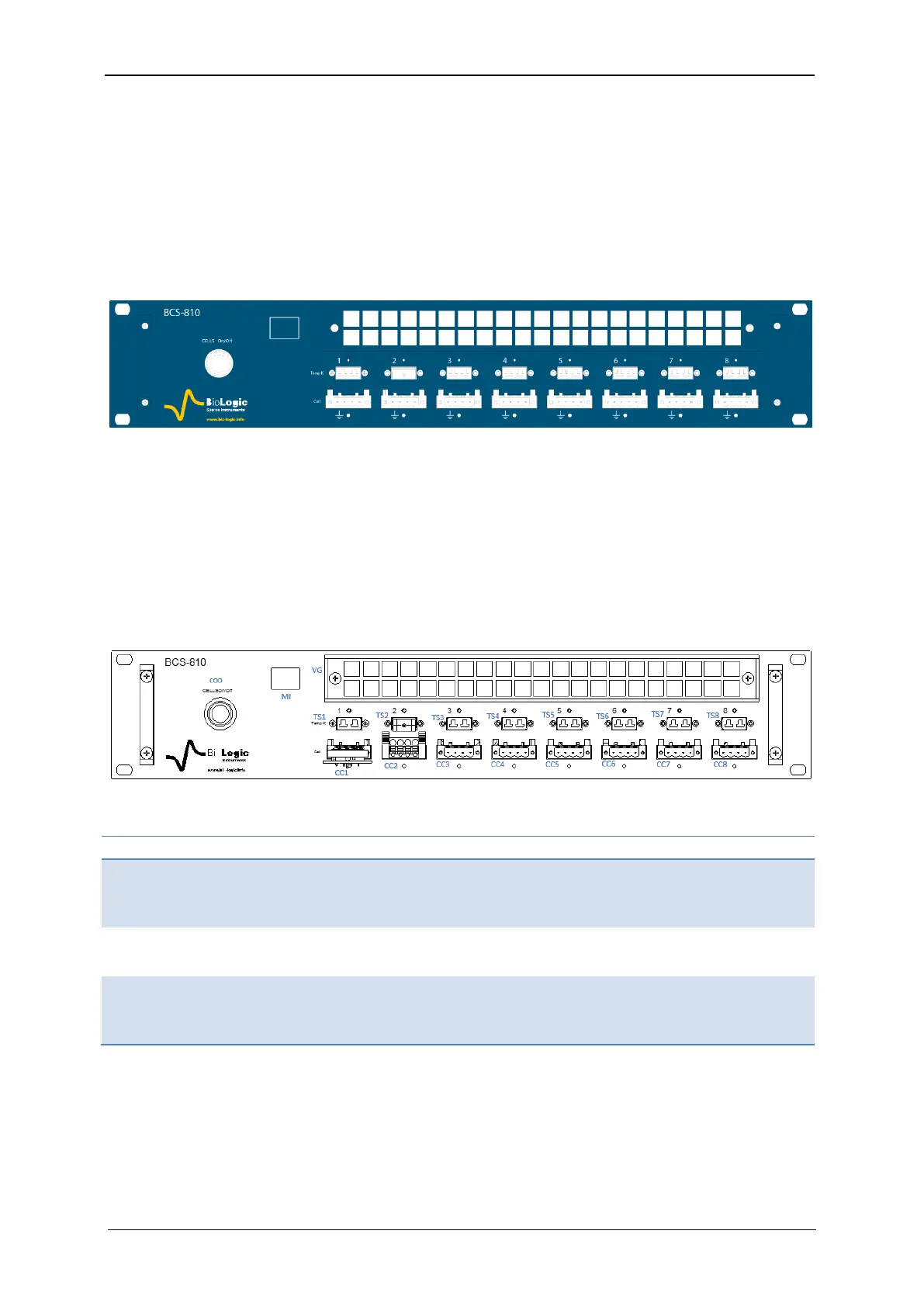
1.2.3 BCS-810 module
A BCS-810 module is referred to a letter (from A to P) and has eight channels numbered
from the left to right (Fig. 8).The letter is located in the left of the front panel (in the white
square), between the Cell on/off button and the ventilation grid.
Each channel can be set, run, paused or stopped, independently of the others, using identi-
cal or different test protocols. Any setting of any channel can be modified during a run, with-
out the need to stop and restart the experiment. The channels can also be grouped and run
synchronously.
Fig. 8: BCS-810 front panel.
A CELL On/Off button is available on the front panel of the BCS-810 module. This button
enables or disables the power output of the 8 channels of the BCS-810 module, not the full
cabinet. If the button is off, all of the channels in the module are switched off.
Every channel is equipped with a K-type thermocouple connection for monitoring cell tem-
perature on that particular channel.
1.2.3.1 BCS-810 front panel detailed description
A BCS-810 has a front panel height of 2U with a ventilation grid on the top, eight K-Type
thermocouple inputs on the middle and eight cell channel connectors on the bottom.
Table 5: Detailed BCS-810 front panel description
Thermocouples input, Type K,
Accuracy: ± 2°C, Measurement
range: -25/+200°C