6
1.1 How to read this manual?
The aim of this manual is to guide the user through the instrument’s installation and configu-
ration. This manual is composed of several chapters.
The first part is a general description of the instruments.
The second and third parts describe the hardware installation and how to install the software
and how to configure the computer.
The fourth and the fifth parts cover how to connect the instrument to the computer and how
to connect the instrument with the cell.
The sixth chapter deals with the advanced features.
Maintenance is described in the eighth part.
Finally, technical specifications are shown in the last parts.
WHEN A USER RECEIVES A NEW UNIT FROM THE FACTORY, CURRENT VERSIONS OF THE SOFTWARE
AND FIRMWARE ARE ALREADY INSTALLED. THE INSTRUMENT IS READY TO BE USED. IT DOES NOT
NEED TO BE UPGRADED.
1.2 Modules description
1.2.1 BCS-COM module
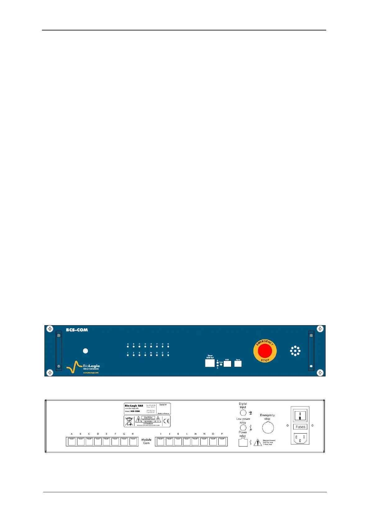
The BCS-COM communication module is equipped with Ethernet, USB and Tera Term con-
nectors (see Fig. 3). The USB and Tera Term connections are only used for factory service.
The Ethernet port is for connecting the BCS-COM with the Local Area Network (LAN) or di-
rectly to a computer.
One Emergency Stop button for the unit is also available on the front panel. This emergency
button turns off the power of all connected units. This button is connected with the PDU unit
trough a four-pin circular connector on the rear panel (see Fig. 18).
Sixteen green leads in the front panel, identified with letters A through P, indicate which of
the BCS-8xx modules are connected with the communication module (illuminated means
connected).
The BCS-COM is equipped, on the rear panel, with sixteen RJ45 connectors (labelled from A
to P) intended to communication connections with the BCS-8xx modules. The rear panel is
also equipped with a digital input (non isolated), and connectors for a low power normal open
contact (optoMOS low power relay) and an isolated power contact (opto-Triac) (see table 2).
Fig. 3: BCS-COM Front panel.
Fig. 4: BCS-COM rear panel.