27
2.4.2 North American model
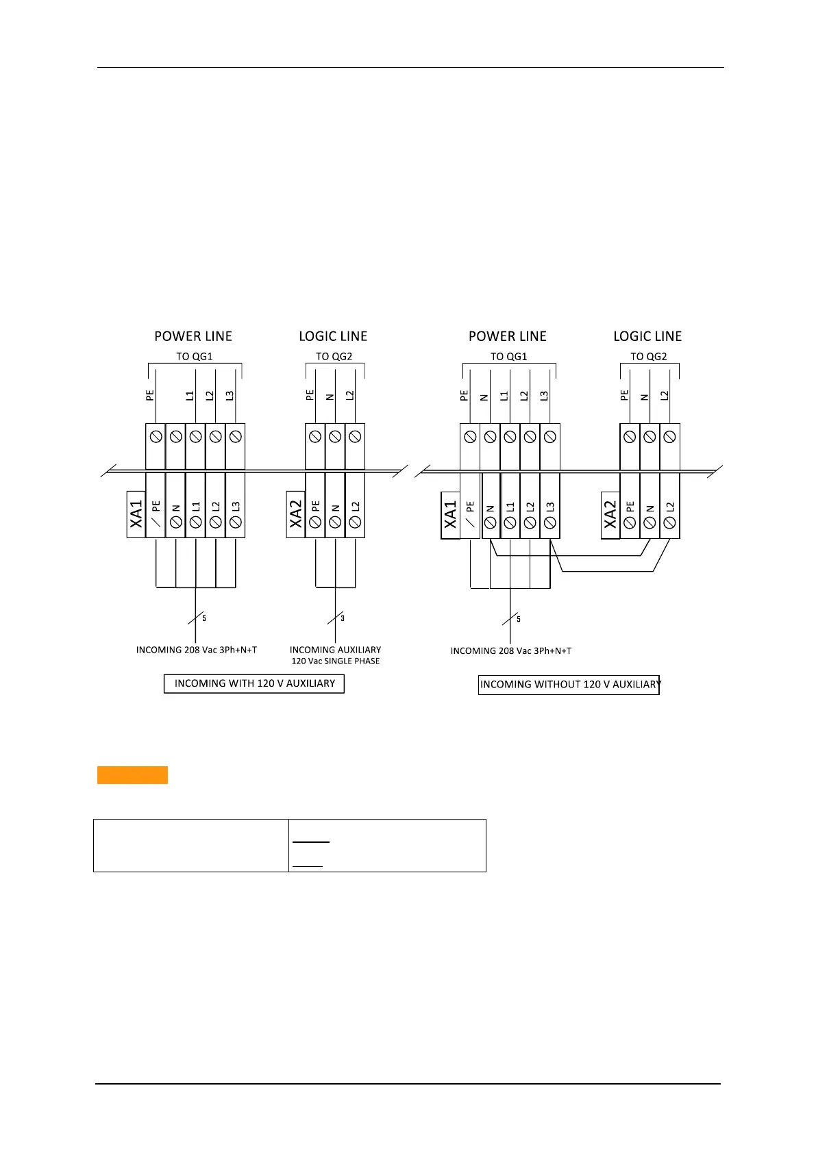
(Split phase line to line)
Fig. (in 10.2 Appendix) exhibits a three-phases split simplified diagram
Fig. 26: Wiring diagram of the North American model of PDU with/without UPS system.
Caution !:
Before power up the module, check that the voltage between phases is lower than 260 VAC
(*) : AWG : American Wire Gauge
2.5 Power supply connections
Power supply connections are on the rear panel of the BCS-8xx modules. The BCS-COM
communication module and all of the BCS-815 (and BCS-810/805) modules can be connect-
ed to the BCS-PDU power distribution module if more than two BCS-815 modules are avail-
able in the BCSC-38U and BCSC-24U cabinets. BCS-COM and BCS-805/810 may be con-
nected to power strip placed in the bottom of the BCSC-24U and BCSC-12U. When more
than two BCS-815 are installed in the BCSC-38U/24U cabinet, a BCS-PDU is required and