29
2.6 Communication Connections
The communication module, BCS-COM, is connected (via Ethernet connections) to the com-
puter/s and to the BCS-8xx modules via RJ45 ports.
On the front panel the communication module there is one Ethernet port for connection be-
tween the computer and the instrument. As mentioned above, the front panel also contains
USB and Tera Term plugs, both plugs are only used for factory service.
The connections between the BCS-8xx modules and the communication module are
achieved through sixteen RJ45 connectors located on the back side of the BCS-COM. These
ports are labelled from A to P.
The communication between the BCS-COM and the PC follow a standard IP protocol, the
communication between the BCS-COM and the BCS modules follow a proprietary protocol.
Caution !:
In order to allow a robust communication, the cables between BCS-COM and the
BCS modules must be shorter than 2m and at the Cat6 norm.
Using a USB to Ethernet adapter is not recommended.
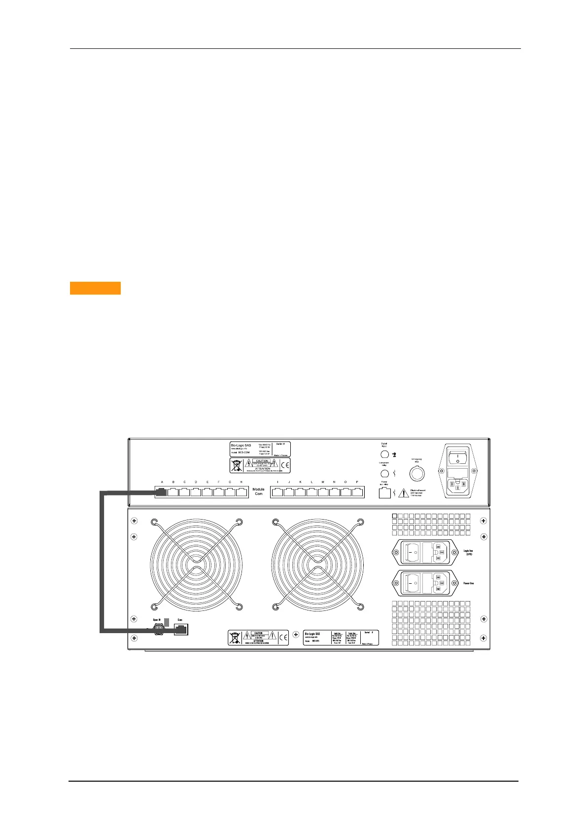
2.6.1 Connection between BCS-COM and the BCS-8xx modules
As mentioned above the communication connection between the communication module and
the BCS-8xx modules is done through the RJ45 port located on the rear panel of the BCS-
COM module as shown in Fig. 28.
Fig. 28: RJ45 connection between the BCS-COM and BCS-815 (rear panel).
2.6.2 Connection between BCS-COM and the computer
Depending on your local installation, you can use a direct connection (one PC to one instru-
ment) or a network connection (one or several PCs to one or several instruments).