BCS-8xx series installation manual
5.4 Cell cable to a battery cell.
This paragraph explains how to connect a channel to a cell using the standard cables pro-
vided with the instrument.
In the standard configuration, a cell cable has four leads which connect to the electrochemi-
cal cell: two leads which carry current (power leads, banana plug 4mm) and 2 which meas-
ure the potential (sense leads, banana plug 2 mm). To be easily identified, each lead has an
associated colour and label as follows:
Sense: RED – for the control and measurement of the positive electrode potential.
Sense BLUE – for the control and measurement of the negative electrode potential.
Power: RED – for the current control and measurement flowing through the positive
electrode.
Power: BLUE– for the current control and measurement flowing through the negative
electrode.
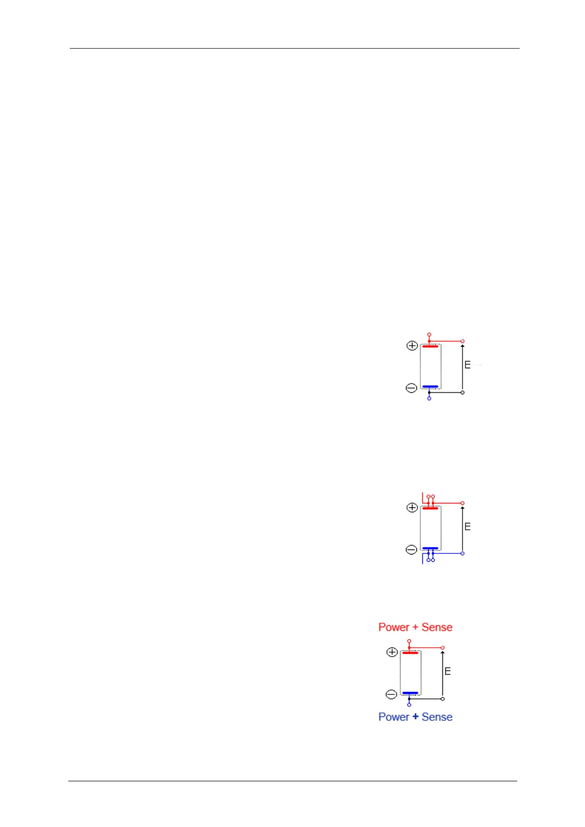
5.4.1 Two electrode connection to a battery cell
The positive electrode of the battery is connected to the red
Power + Sense. The potential control or measurement is
performed between the blue Sense and the red Sense and
the controlled or measured current crosses the cell from the
red Power to the blue Power. So the negative electrode must
be connected to the blue Sense + Power.
Fig. 53: Electrode connection
to a battery cell.
5.4.2 Four electrode connection to a battery cell
4-point probes method is also possible. The red Power and
Sense are connected separately to positive electrode of the
battery. The potential control or measurement is performed
between the blue Sense and the red Sense and the con-
trolled or measured current crosses the cell from the red
Power to the blue Power. So the blue Sense and Power must
be connected also separately to the negative electrode.
Fig. 54: Electrode connection
to a battery cell.
5.4.3 Electrode connection using Coin Cell Holder
The coin cell holders CCH-120/124 allow 2-point measure-
ments. The upper electrical contact is dedicated for the con-
trol and the measurement of positive potential and current.
The lower electrical contact allows the control and measure-
ment of negative voltage and current.
The coin cell holder CCH-8 allows a 4-point measurements.
Fig. 55: Two electrode con-
nection used with Coin cell