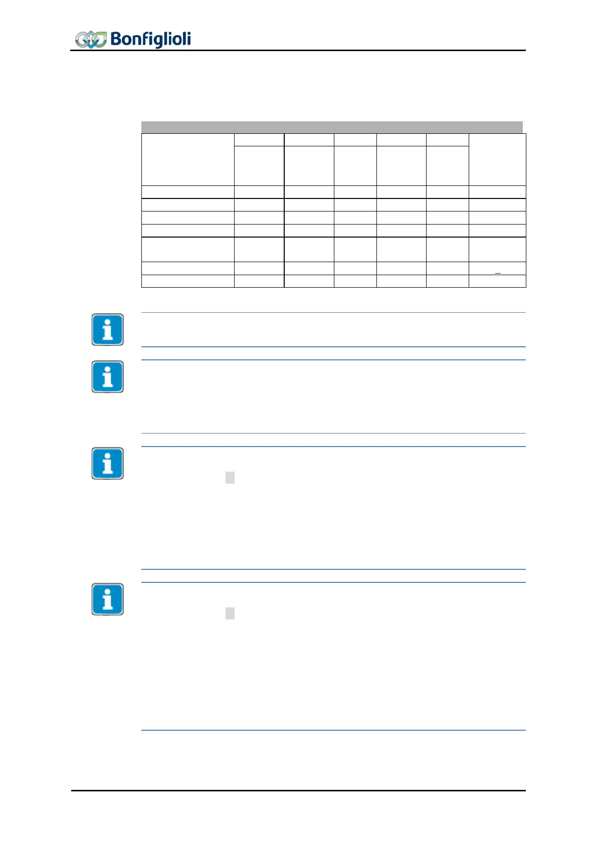
The device control commands are triggered by the following bit patterns in the Con-
trol word.
Transitions
operation
stop
(Low
voltage
Transition 3 (command “Switch On” [0x07]) will only be processed if Bit 4 “Voltage
enabled” of the Status word is set.
Transition 4 (Command “Enable operation” [0xF]) will only be processed if the release
is set via the hardware contacts STO.
If the hardware release via STO is not set, the frequency inverter will remain in status
“Switched On” [0x33] until the hardware release via STO is present.
In status “Operation enabled
” [0x37], the device will switch to status “Switched On
”
[0x33] internally once the hardware release via STO is reset.
In configurations with Motion Control (parameter Configuration 30 = x40), the fol-
lowing must be noted:
• Transition 4’ is not available.
• In status “5-Operation enabled [0x37]” an additional start signal must be pr
o-
vided via bits from the “High Byte” of the control word in order to start a
movement of the motor. For a description of the start signal for this “Motion
Control Interface” (MCI), refer to Chapter 11.4. The
Modes of operation
fun
tion is available for switching to other MCI modes.
• Digital inputs (STOA and STOB) must be set. Start clockwise and Start ant
i-
clockwise have no function in these configurations.
In configurations without Motion Control (parameter Configuration 30 ≠ x40), the
following must be noted:
• Transition 4’ will only be processed if Bit 4 “Voltage enabled” of the status
word is set. This feature is downward-compatible with older software ver-
sions.
• The frequency inverter can only be controlled if the logic operation is true.
The logic inputs for Start Clockwise and Start anticlockwise can be connected
directly with “On” or “Off” (parameter
Start Clockwise 68 and Start Anti-
clockwise
69).
Digital inputs (STOA and STOB) must be set.
This results in:
Release: (= STOA and STOB) AND (Start clockwise OR Start Anticlockwise)
70 CM-PROFINET 10/13
 Loading...