Operating Instructions ACTIVE 06/07164
164 Operating Instructions ACTIVE 06/07
The function selected via the parameter Operation Mode 440 defines the behavior of
the technology controller
Operation mode 440 Function
0 - Off
The technology controller is switched off, the refer-
ence value specification is done via the reference per-
centage channel.
1 - Standard
For pressure and volume flow control with linear oper-
ating behavior and actual value monitoring.
2 - Liquid Level 1
Contents level control at defined motor speed with
actual value missing.
3 - Liquid Level 2
Contents level control at defined motor speed with
actual value missing or high control deviation.
4 - Speed controller
Speed control with analog feedback of the actual
speed.
5 -
Indirect volume flow
control
Volume flow control with square rooted actual value.
The behavior of the technology controller corresponds to a PI controller with the com-
ponents
− proportional component Amplification 444
− integral component Integral time 445
The sign of the amplification determines the direction of control, i.e. with a rising ac-
tual value and pos. sign of the amplification, the output frequency is reduced (e.g. in
pressure control). With a rising actual value and neg. sign of the amplification, the
output frequency is increased (e.g. in temperature control systems, refrigerating ma-
chines, condensers).
The integral component can be used to reduce the steady-state control deviation (de-
viation between actual value and reference value) over a period of time. If the inte-
gral component is too dynamic
1)
the system will be unstable and oscillates. If the in-
tegral component is too passive
2)
the steady-state control deviation will not be cor-
rected adequately.
Therefore the integral component must be adjustet installation-dependent.
1)
Dynamic behavior: fast correction of deviations.
2)
Passive behavior: slow correction of deviations.
Parameter Max. P-Component 442 limits the frequency change at the controller out-
put. This prevents oscillations of the system at steep acceleration ramps.
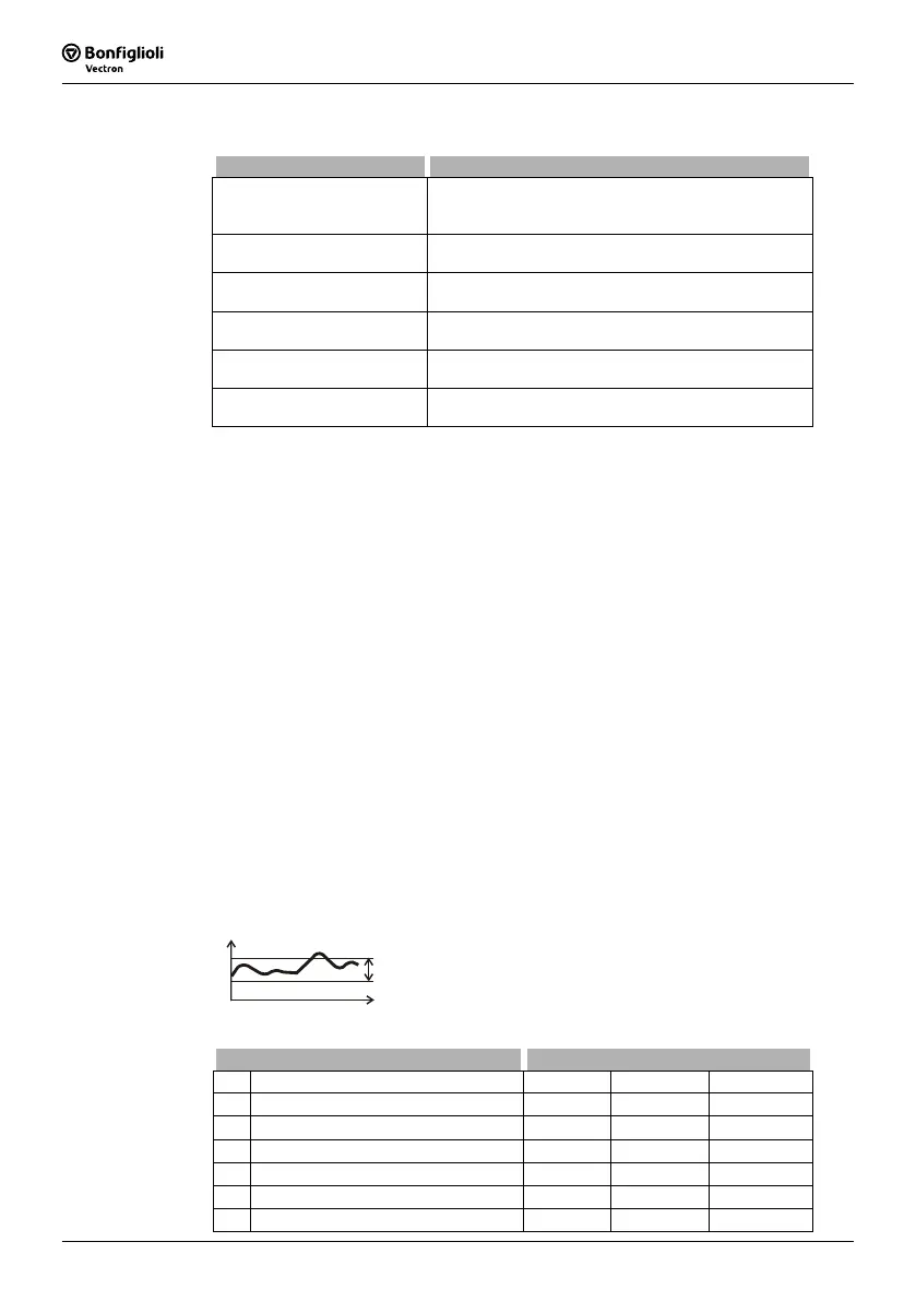
Via Parameter Hysteresis 443 changes of the integral component in a specified range
(hysteresis band) can be rejected. This causes more passiv behavior of the technology
controller and helps to filter noise signals of the controller actual value and to mini-
mize control corrections.
f
Hysteresis
44
Parameter Settings
No. Description Min. Max. Fact. sett.
441 Fixed Frequency -999.99 Hz +999.99 Hz 0.00 Hz
442 max. P-Component 0.01 Hz 999.99 Hz 50.00 Hz
443 Hysteresis 0.01 % 100.00 % 10.00 %
444 Amplification -15.00 +15.00 1.00
445 Integral Time 0 ms 32767 ms 200 ms
446 Ind. Volume Flow Control Factor 0.10 2.00 1.00
 Loading...


