Synchronization between several drives must be performed at high updating rates in
order to guarantee optimum results. In the transmitter of the TxPDO object, set a low
value for the time (e.g. TxPDO1 Time 931). If you use the SYNC function of System
Bus, set parameter
SYNC time 919 to a lower value.
Note that, due to these settings, the bus load of the system bus must provide for
sufficient reserves for proper operation.
System Bus is described in the manuals of the extension modules with System Bus
interface.
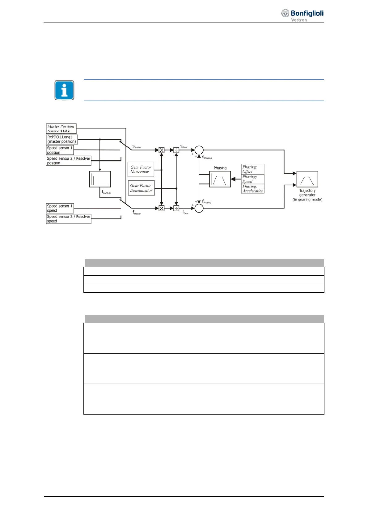
Block diagram: electronic gear and phasing function
The master position and speed are multiplied by the
gear factor
. When phasing is start-
ed, the phasing profile is added to the master speed until the phasing offset is reached.
The
Gear factor
is defined via the following parameters:
Resync. on Change of Gear-Factor
Phasing
is defined via the following parameters:
1125.2
1125.3
1126.2
1126.3
1127.2
1127.3
Start electronic gear and phasing function
The electronic gear is started by control word bit 4 “Start electronic gear”. The drive
accelerates according to parameter
Override Profile Acceleration 1457
.
Once the
slave speed is coupled into the master, sta
tus word bit 10 “Target reached/In
The conditions for “In Gear” status are set via parameters In Gear'-
Threshold
1168 and In Gear'-Time 1169.
10/13
ACU
Modbus/TCP 113