13
Front and rear panels
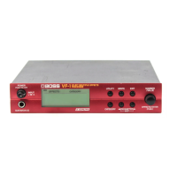
Rear panel
fig.0-002
(10) AC Adapter jack
Connect the included AC adapter to this jack.
(11) MIDI IN/OUT
MIDI connectors (in/out)
An external MIDI device can be connected here to transmit/
receive MIDI messages to/from the VF-1. Use a MIDI cable
(sold separately) to make connections.
(12) EXP PEDAL/CTL 1,2
Expression pedal/Control 1,2 jack
Either an expression pedal or a foot switch can be connected
here, and used to step up/down through patch numbers, or
for realtime control of parameters. If a Roland PCS-31 (sold
separately) is used, you can use its two foot switches to
simultaneously control different parameters.
(13) DIGITAL OUTPUT
Digital output connector (coaxial)
A digital audio signal is output from this connector.
Use a video cable (75 Ω unbalanced) to make connections.
(14) OUTPUT L (MONO) /R
Output jacks
These are the output jacks for the audio signal. Connect them
to your amp or mixer.
Use audio cables (separately sold) to make connections.
(15) LEVEL
Level switch
Switch simultaneously regular input and output.
(16) INPUT L (MONO) /R
Input jacks
These are the audio input jacks. Connect them to a keyboard
or the like.
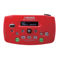
(17) Cord Hook
To prevent the AC adapter cord from being accidentally
disconnected, wrap the cord around this hook.
* If you wish to attach the rack mount adapter (RAD-50; sold
separately), refer to the manual of the rack mount adapter
(RAD-50).
* If you will be using the VF-1 by itself, without using the rack
mount adapter (RAD-50; sold separately), attach the included
rubber feet as shown in the diagram.
fig.0-03
(
10
) (
11
)(
12
) (
13
) (
14
)(
15
) (
16
)
(
17
)