Note:
is ON. This should be carried out in the Power OFF Condition only.
For removing the IO Modules,
plastic
screws, after that press the lock on
to remove it. Failing to do so will damage the IO Card. Please follow
The Maximum Torque for the metal screw is 3Kg
Calibration should be carried out by a qualified Engineer with qualified equipments
only.
Thermocouple inputs requires 1 hour initial warm up time during initial setup.
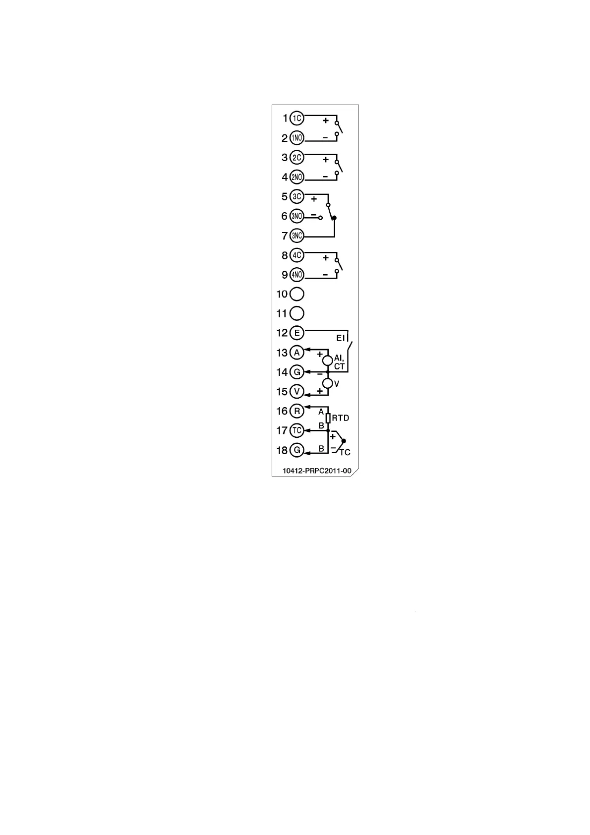
2-1.Process Control Card Wiring Diagram
dules should not be removed or Inserted to the device when the Power
is ON. This should be carried out in the Power OFF Condition only.
For removing the IO Modules,
First remove the metal screws then
screws, after that press the lock on
the top and bottom of the Card and
to remove it. Failing to do so will damage the IO Card. Please follow
for more information.
The Maximum Torque for the metal screw is 3Kg
-
screw is 0.8Kgf-cm (.7in-lb).
Calibration should be carried out by a qualified Engineer with qualified equipments
Thermocouple inputs requires 1 hour initial warm up time during initial setup.
Page 21 of 113
dules should not be removed or Inserted to the device when the Power
is ON. This should be carried out in the Power OFF Condition only.
First remove the metal screws then
remove the
the top and bottom of the Card and
pull
to remove it. Failing to do so will damage the IO Card. Please follow
the Recorder
-lb) and the Maximum
Calibration should be carried out by a qualified Engineer with qualified equipments
Thermocouple inputs requires 1 hour initial warm up time during initial setup.
 Loading...