Page 86 of 113
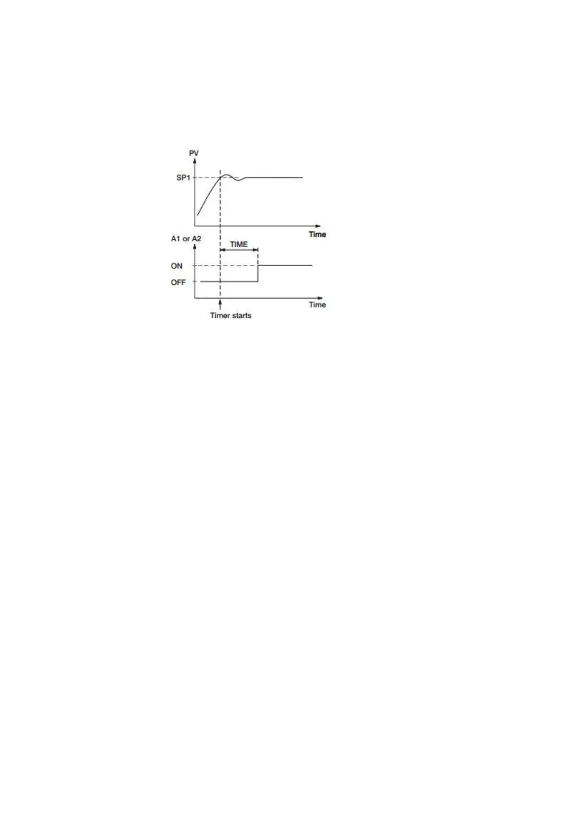
out. The timer relay will remain unchanged until time out. The dwell timer operation is shown as
following diagram.
Figure 4-35.Dwell Timer
If alarm 1 is configured as dwell timer, A1SP, A1DV, A1HY and A1MD are hidden. Same
case is for alarm 2.
Example
Set A1FN=TIMR or A2FN=TIMR but not both. Adjust TIME in minutes .A1MD (if
A1FN=TIMR) or A2MD (if A2FN=TIMR) is ignored in this case.
4.3.1.1.4.12 Process Alarms
A process alarm sets an absolute trigger level (or temperature). When the process (could
be PV1, PV 2 or PV1-PV2) exceeds that absolute trigger level an alarm occurs. A process alarm is
independent from set point. Adjust A1FN (Alarm 1 function) in setup menu. One of 8 functions can
be selected for process alarm. These are: PV1.H, PV1.L, PV2.H, PV2.L, P1.2.H,
P1.2.L, D1.2.H, D1.2.L.
When the PV1.H or PV1.L is selected the alarm examines the PV1 value. When the
PV2.H or PV2.L is selected the alarm examines the PV2 value.
When the P1.2.H or P1.2.L is selected the alarm occurs if the PV1 or PV2 value
exceed the trigger level. When the D1.2.H or D1.2.L is selected the alarm occurs if the PV1-PV2
(difference) value exceeds the trigger level. The trigger level is determined by A1SP (Alarm 1 set
point) and A1HY (Alarm 1 hysteresis value) in configuration for alarm 1. The hysteresis value is
introduced to avoid interference action of alarm in a noisy environment. Normally A1HY can be set
with a minimum (0.1) value. A1DV and/or A2DV are hidden if alarm 1 and/or alarm 2 are set with
process alarm.
Normal Alarm: A1MD = NORM
 Loading...