6.11 ASI (Optional module for VB220)
For each VB242 module the user selects whether two inputs (inputs 1 and 2) should be
permanently monitored in parallel, or if all enabled inputs should be monitored
sequentially in a round-robin fashion. This selection is made in the Setup – ETR view.
Note that probe hardware version 3 (HW3) is required for simultaneous monitoring of
two ASI signals from a single VB242 module. The hardware version of a probe is found
in the About – Release info view.
If one optional VB242 ASI interface module is present in the chassis, the associated
ASI tabs will be labelled ASI 2 and ASI 3, when continuous monitoring mode is
selected. In round-robin mode only the ASI 2 tab will be visible, as only one ASI stream
from the VB242 is monitored at any time.
If two optional VB242 ASI interface modules are present in the chassis, the associated
ASI tabs will be labelled ASI 2, ASI 3, ASI 4 and ASI 5, when continuous monitoring
mode is selected. In round-robin mode the ASI 2 and ASI 3 tabs represent the two
modules.
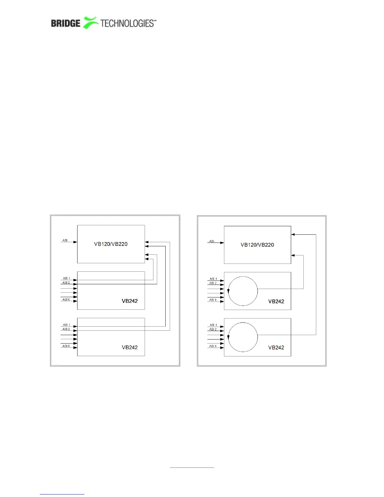
The figure above illustrates signal routing for two VB242 modules in one chassis, for
continuous monitoring mode and round-robin mode respectively. The circles represent
round-robin functionality, each ASI input signal being switched to the chassis back
plane sequentially. In continuous mode five ASI signals may be analysed in parallel by
the probe module, whereas in round-robin mode three ASI signals are analysed in
parallel.
PROBE USERS' MANUAL VERSION 5.0
2014 © BRIDGE Technologies Co AS - Bentsebrugata 20 - N-0476 Oslo, Norway - tel: +47 22 38 51 00 -
www.bridgetech.tv
164