Table of Contents
1 INTRODUCTION..............................................................................................................7
1.1 About the Probe...........................................................................................................7
1.1.1 Probe - Overview.................................................................................................7
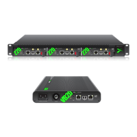
1.1.2 VB20 and VB220...................................................................................................8
1.1.3 Probe - Functionality............................................................................................9
1.2 How to use this manual...............................................................................................10
2 PRINCIPLE OF OPERATION.........................................................................................11
3 SAFETY.........................................................................................................................13
4 INSTALLATION AND INITIAL SETUP.............................................................................14
4.1 Quick Installation Guide.............................................................................................14
4.2 The Enhanced Chassis (EC)......................................................................................14
4.2.1 Dual Power Supply.............................................................................................15
4.2.2 Cooling System..................................................................................................15
4.3 The Enhanced Chassis -48V DC version (ECDC).....................................................16
4.3.1 Dual Power Supply.............................................................................................16
4.3.2 Cooling System..................................................................................................17
4.3.3 ECDC Power Supply...........................................................................................17
4.4 Serial Number Location.............................................................................................18
4.5 Portable chassis (VB20).............................................................................................19
4.5.1 AC Power Supply ...............................................................................................19
4.5.2 Cooling System..................................................................................................19
4.5.3 Serial number location.........................................................................................19
4.5.4 Interfaces............................................................................................................19
4.6 The ACC/DCC Hardware (VB220).............................................................................20
4.6.1 Cooling System..................................................................................................20
4.6.2 ACC Power Supply.............................................................................................20
4.6.3 DCC Power Supply............................................................................................21
4.6.4 Serial Number Location......................................................................................21
4.7 The Hardware Modules and Connectors (VB220)......................................................22
4.7.1 The Probe Module...............................................................................................22
4.7.2 The VB242 ASI Input Module (VB220 option).....................................................23
4.7.3 The VB250 COFDM Demodulator Module (VB220 Option)................................24
4.7.4 The VB252 COFDM Dual Demodulator Module (VB220 Option)........................25
4.7.5 The VB260 QAM Demodulator Module(VB220 Option)......................................26
4.7.6 The VB262 Dual QAM/8VSB Demodulator Module (VB220 Option)..................27
4.7.7 The VB270 DVB-S/S2 Demodulator Module (VB220 Option).............................28
4.7.8 The VB272 dual DVB-S/S2 Demodulator Module (VB220 Option).....................29
4.7.9 The VB273 DVB-S/S2 Redundancy switch (VB220 Option)................................30
4.8 Installing the Unit in a Rack (VB220).........................................................................34
4.8.1 Default Installation - Connectors at the Front of Rack........................................34
4.8.2 Optional Installation - Connectors at the Rear of Rack.......................................34
4.8.3 Optional Installation - Mid-Mounting...................................................................35
4.9 Powering up the Unit.................................................................................................35
4.10 Initial Configuration.................................................................................................. 36
4.10.1 Initial Configuration Using the Pre-Set IP-Address...........................................36
4.10.2 Initial Configuration Via Serial Console Emulated Over USB...........................36
4.10.3 Verifying Correct Initial Setup of the Probe.......................................................40
4.10.4 Initial Setup Troubleshooting............................................................................41
5 QUICK SETUP GUIDE...................................................................................................42
5.1 Basic Setup: All Interfaces.........................................................................................42
5.2 Input Signal Definitions..............................................................................................42
5.2.1 ASI Input ...........................................................................................................42
5.2.2 Ethernet Input (IP Option Only)..........................................................................42
5.2.3 OTT Input (OTT Engine Option Only).................................................................43
5.2.4 Demodulator Input(VB220).................................................................................43
5.3 Monitoring: All Interfaces............................................................................................44