4.8 Installing the Unit in a Rack (VB220)
The following equipment is needed for hardware installation of the unit:
• 4 rack screws
• A screw driver for the rack screws
• For rear mounting: a size 2 Phillips screwdriver for rack ear screws
• For -48 VDC PSU: cable soldering equipment
4.8.1 Default Installation - Connectors at the Front of Rack
By default the Enhanced and ACC/DCC chassis are shipped with rack ears for front
mounting of the unit. The rack ears are designed to support the weight of the unit, so
no additional support, like a rack shelf, is needed.
When deciding where to locate the unit, make sure there is sufficient space
surrounding the unit to allow efficient cooling, refer to section 4.2.2 (Enhanced
Chassis) and 4.3.1 (ACC/DCC Chassis).
Use four rack screws to install the unit in the rack.
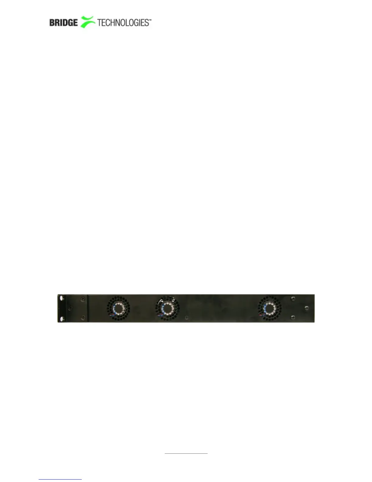
4.8.2 Optional Installation - Connectors at the Rear of Rack
For rear mounting of the chassis, the rack ears should be moved prior to rack
installation. Unscrew the six size 2 Phillips screws holding the rack ears, and move the
six screws covering the rear mounting holes to the front mounting holes. Remount the
rack ears at the rear end of the unit.
Install the unit as described in section 4.5.1.
Figure 6: Rack Ears Mounting – Side View of ACC/DCC Chassis
PROBE USERS' MANUAL VERSION 5.0
2014 © BRIDGE Technologies Co AS - Bentsebrugata 20 - N-0476 Oslo, Norway - tel: +47 22 38 51 00 -
www.bridgetech.tv
34