License.
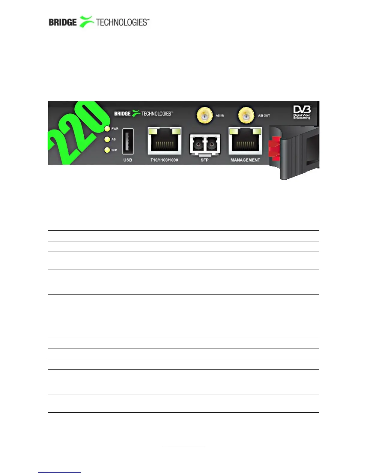
4.7 The Hardware Modules and Connectors (VB220)
The probe module is equipped with the following connectors:
4.7.1 The Probe Module
USB: USB serial port emulator for initial set-up of the probe – Type A
ASI INPUT: ASI transport stream input – 75 ohm SMB female
ASI OUTPUT: ASI transport stream output – 75 ohm SMB female
SFP: Alternative SFP input used when connecting to optical
networks
T10/100/1000:
(Video – eth0)
For monitoring a 10/100/1000 electrical/copper signal – RJ-45.
The probe can only monitor either the SFP input signal OR the
T10/100/1000 input signal (selected from software).
MANAGEMENT:
(Management –
eth2)
For optionally running management of the probe on a separate
network – RJ-45. This interface supports T10/100.
A number of LEDs serve the following purposes:
POWER: Green power LED
ASI: Green LED indicating ASI sync
SFP LINK: Green LED indicating SFP link status
T10/100/1000: The green LED indicates link. The yellow LED indicates that the
interface is receiving data (RX). Both LEDs are off if input is
taken from the SFP module.
MANAGEMENT: The green LED indicates link. If the yellow LED is active the
speed is 100Mbps – otherwise the speed is 10Mbps.
PROBE USERS' MANUAL VERSION 5.0
2014 © BRIDGE Technologies Co AS - Bentsebrugata 20 - N-0476 Oslo, Norway - tel: +47 22 38 51 00 -
www.bridgetech.tv
22