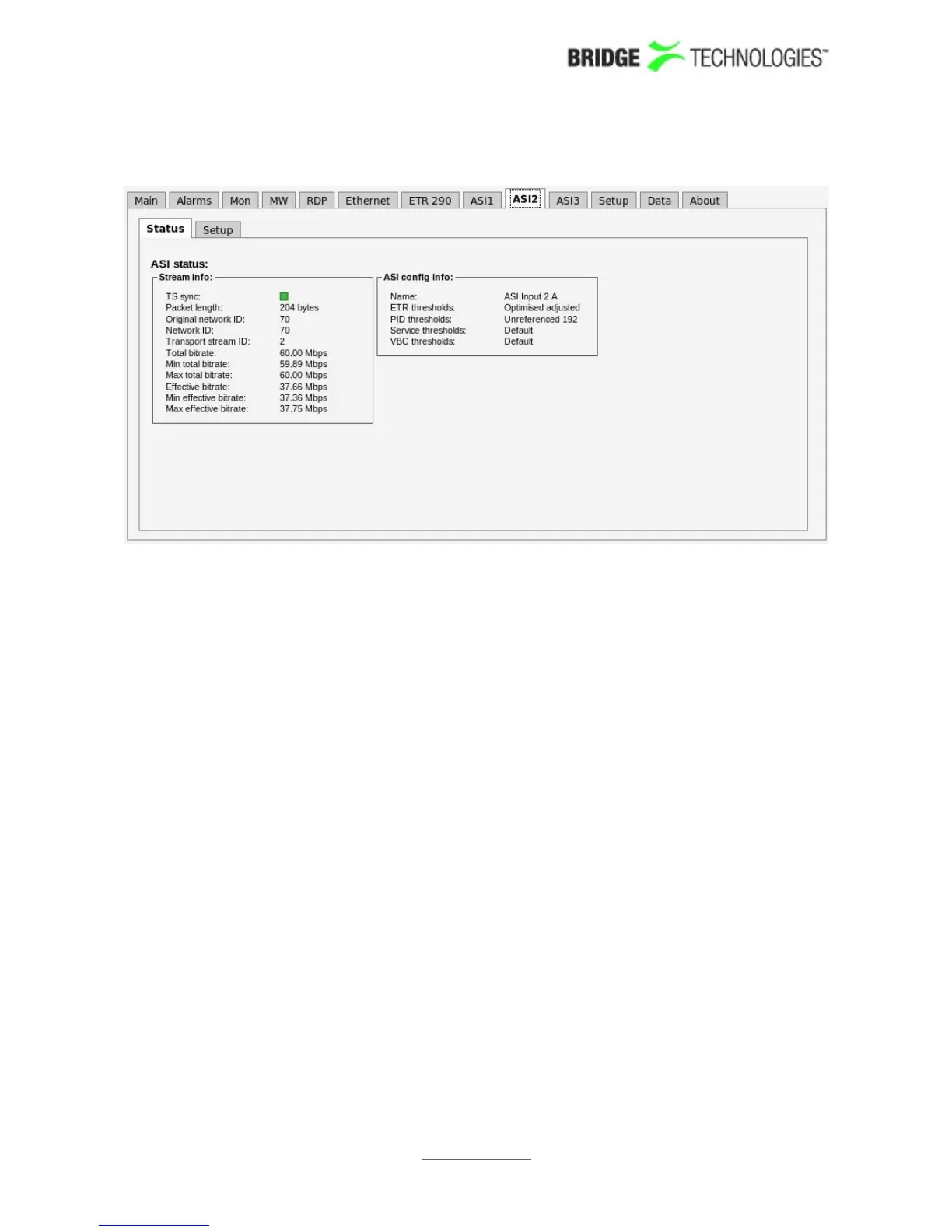
6.11.1 ASI - Status
The ASI view displays an overview of the ASI input signal contents, in addition to
listing the threshold templates currently assigned to the ASI signal. Refer to section
6.10.1 for a description of the measurement parameters in this view. Additional ASI
measurements are found in Compare and ETR 290 views.
The screenshot above shows the GUI for a chassis with one optional VB242 module
installed, and continuous monitoring mode selected (Setup – ETR view). ASI 1 is the
ASI input of the probe module. ASI 2 and ASI 3 are inputs 1 and 2 of the VB242
module.
If ASI round robin mode is selected, threshold selections for all VB242 ASI inputs are
accessed via the ASI 2 tab, and the ASI 3 tab will not be visible – refer to next section.
PROBE USERS' MANUAL VERSION 5.0
2014 © BRIDGE Technologies Co AS - Bentsebrugata 20 - N-0476 Oslo, Norway - tel: +47 22 38 51 00 -
www.bridgetech.tv
165