5. STANDARD ADJUSTMENT (MACHINE HEAD)
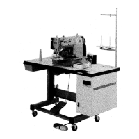
7. After adjusting, tighten the screw of the thread thread
trimmer lever u so that there is no vertical play in
the thread trimmer lever u.
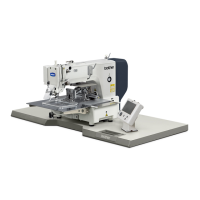
8. Let in the air and check that the clearance between
the thread trimmer lever roller i and the level sur-
face of the thread trimmer cam o is 0.2 mm.
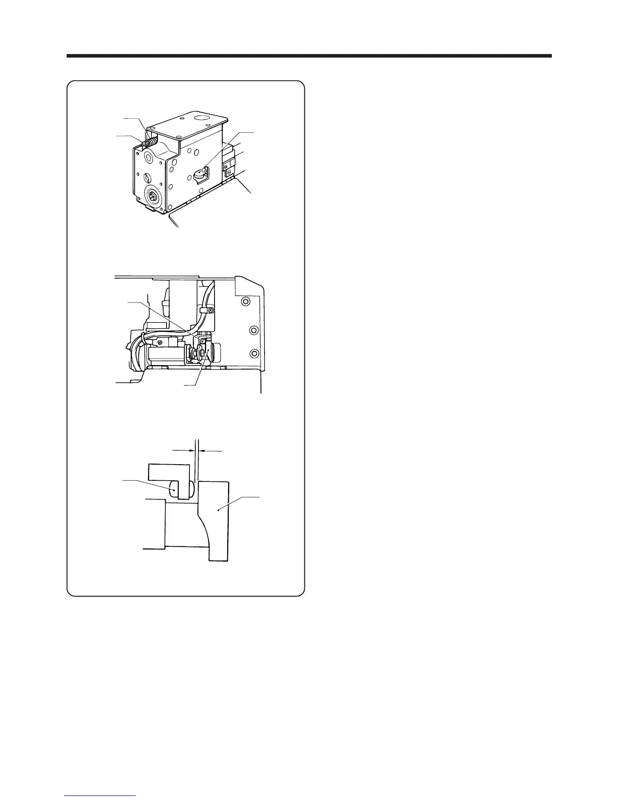
9. Place the thread trimmer spring t onto the spring
hook y, and then install the BM-front cover e with
the six screws r.
―42―
BAS-705
t
y
u
i
o
i
o
0.2mm